
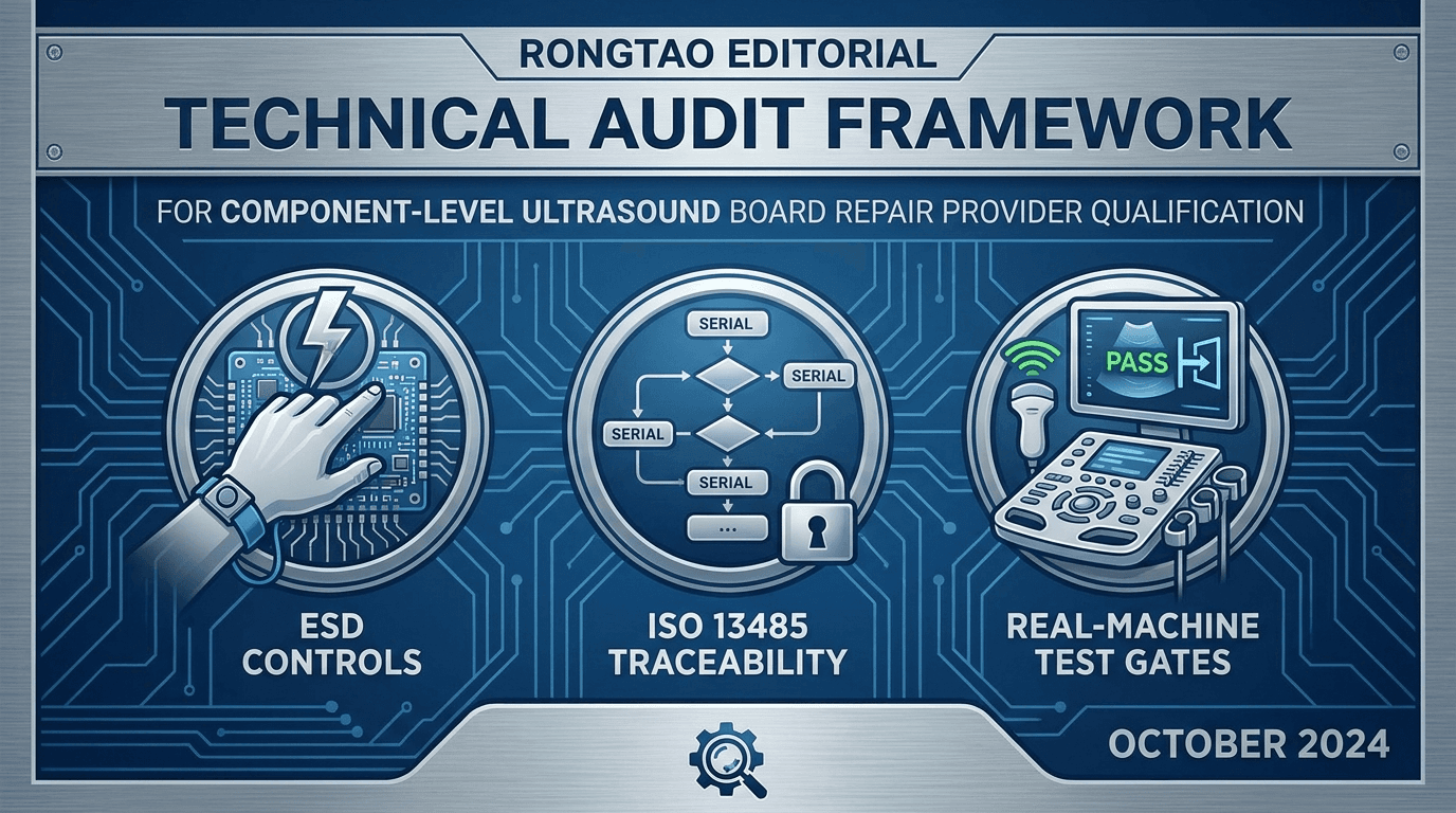
What is the difference between a board swapper and a true component-level repair bench?
In the medical imaging aftermarket, suppliers frequently market 'ultrasound board repair services.' However, the technical execution behind this label falls into two vastly different operational archetypes: board-level swap brokers and component-level micro-engineering repair facilities. Understanding this operational boundary is essential for healthcare technology managers (HTM), biomedical engineering departments, and independent service organizations (ISOs) seeking long-term equipment stability.
A 'board swapper' (or core broker) does not repair circuit boards at the schematic level. When a customer sends in a defective motherboard, transmitter board, or continuous wave (CW) Doppler module, the broker simply extracts a functional board from a dismantled donor system, labels it as 'repaired,' and ships it back. If the donor system possessed latent thermal stress, aged electrolytic capacitors, or marginal timing components, those hidden defects remain inside the replacement assembly. Furthermore, board swappers cannot repair rare, high-value, or obsolete circuit boards when donor inventory is unavailable across global markets.
By contrast, a genuine component-level board repair facility performs micro-level failure analysis, circuit-trace restoration, component desoldering, surface-mount technology (SMT) rework, and ball grid array (BGA) reballing directly on the customer's original assembly. This approach preserves the board's original revision history, eliminates supply-chain constraints for obsolete models, and ensures that aged, high-stress passive components are proactively remediated. When evaluating candidate shops, procurement teams should understand [how to write and evaluate a multi-brand board-repair RFQ](/blog/reports/multi-brand-ultrasound-board-repair-rfq-template) to mandate full diagnostic transparency before committing capital.
To illustrate the technical capabilities required, component-level micro-electronics repair involves precise diagnostic equipment and controlled thermal profiles. Engineers utilize multi-channel digital storage oscilloscopes (200 MHz to 1 GHz bandwidth), high-frequency logic analyzers, automated semiconductor curve tracers, and thermal imaging cameras. When dealing with micro-BGA microprocessors or fine-pitch Surface Mount Devices (SMD), the repair bench must employ optical alignment BGA rework stations with closed-loop infrared (IR) preheating zones. Without controlled thermal profiling, thermal shock during desoldering can warp multi-layer printed circuit boards (PCBs) containing internal ground and power planes, rendering the assembly permanently unusable.
Consider the architectural differences across major OEM ultrasound platforms. On GE Logiq E9 and Vivid E9 systems, the GFI (Global Front End) and GTX (Transmitter) boards contain multi-layer interconnects carrying high-voltage pulsers (+/- 100V) in close physical proximity to ultra-sensitive low-noise preamplifier channels. A board swapper encountering a dead channel will simply replace the whole GTX assembly. A component-level bench isolates whether the fault lies in a shorted high-voltage switching diode, a failed gate driver optocoupler, or a degraded decoupling capacitor. By replacing the specific semiconductor junction and inspecting adjacent components for thermal degradation, the component-level shop restores original circuit dynamics without disturbing adjacent calibrated acquisition rails.
Component-level repair also requires controlled materials and processes. For soldering or BGA work, the provider should identify the original assembly requirements, select a compatible alloy and flux, control the thermal profile and cleaning method, protect moisture- or heat-sensitive components, and inspect the completed joints. Ask for the process qualification and job record rather than assuming one named alloy or solvent is correct for every board.
An additional critical technical distinction lies in automated optical inspection (AOI) and X-ray void analysis. After BGA microprocessors or dense SMT array packages are soldered back onto an ultrasound acquisition board, visual inspection alone cannot verify solder joint integrity beneath the ceramic package. A fully qualified micro-electronics repair facility utilizes 2D/3D X-ray inspection systems to verify that solder ball voiding remains below 15% across all BGA pads, conforming to IPC-A-610 Class 3 medical electronics manufacturing standards. Without X-ray void inspection, hidden bridge shorts or insufficient solder wetting can cause catastrophic board failures weeks after installation.
| Evaluation Criteria | Board Swapper / Broker Model | Component-Level Repair Facility |
|---|---|---|
| Primary Method | Exchanges customer core for a used donor board pulled from decommissioned systems. | Isolates and replaces specific failed micro-components on customer's original board. |
| Diagnostic Depth | Limited to high-level go/no-go system boot tests. | Schematic tracing, oscilloscope analysis, thermal imaging, and signal integrity testing. |
| Micro-SMT & BGA Rework | No micro-soldering capability; cannot replace multi-pin ICs. | Optical alignment BGA reballing stations and multi-zone IR reflow profiling. |
| Obsolete Board Support | Fails when donor pool is exhausted for end-of-service (EOS) systems. | Restores original PCB hardware regardless of external inventory availability. |
| Component Refresh | Leaves adjacent aged capacitors and semiconductor junctions untouched. | Replaces failed components plus high-risk adjacent wear items (e.g., power rails, caps). |
| Cost Efficiency | High core-exchange fees tied to whole-assembly market value. | Targeted labor and component costs, typically yielding substantial savings over replacement. |
| Traceability & Records | Provides basic serial swap tags without root-cause documentation. | Delivers detailed engineering failure analysis (FA) report and component lot traceability. |
Which process controls and standards must a board-repair shop be able to prove (ESD, traceability, nonconforming parts)?
Component-level micro-electronics repair requires far more than skilled soldering iron operators. Modern ultrasound systems—such as the GE Logiq E9, Philips EPIQ 7, Siemens S2000, or Canon Aplio i800—utilize dense multi-layer printed circuit boards populated with field-programmable gate arrays (FPGAs), application-specific integrated circuits (ASICs), ultra-low-noise analog-to-digital converters (ADCs), and high-voltage transmitter switches. Operating on these assemblies without strict process governance risks catastrophic electrostatic damage or unrecorded circuit modifications.
When auditing a potential repair partner, buyers must verify three core quality management system (QMS) foundations:
- **ANSI/ESD S20.20-2021 & IEC 61340-5-1 Governance:** Ask for the facility's documented ESD control plan, protected-area boundaries, personnel grounding method, verification/calibration records, training, packaging controls, and corrective-action process 3. The exact controls and limits should come from the facility's risk assessment and implemented program, not a generic checklist copied into a sales document.
- **QMS Scope & Repair Traceability:** FDA QMSR applies to device manufacturers and other regulated entities whose activities fall within 21 CFR Part 820, including remanufacturers; it is not a blanket rule for ordinary servicing. Separately, an ISO 13485-certified shop should show how its certificate scope and documented procedures cover the service, and buyers should contract for board identity, replaced-component identity where available, repair actions, tester/system ID, and release records 1 2.
- **Control of Nonconforming Product (Clause 8.3):** Defective components removed from customer boards, as well as nonconforming incoming replacement stock, must be physically isolated in designated quarantine bins. This prevents accidental re-insertion of faulty parts into repair workflows or customer equipment.
Auditing ESD protection requires records and observation rather than verbal assurances. Review the defined ESD-protected area, grounding and personnel-control methods, verification frequency, equipment status, handling of insulators, and shielding/packaging steps. Compare any numeric limits with the provider's current controlled procedure and the cited standard rather than treating the examples below as universal requirements.
A detailed audit of an electronics bench environment should inspect five physical ESD control checkpoints:
- **1. Workstation Grounding Verification:** Request recent verification records for common-point grounding, work surfaces, and grounded tools under the provider's controlled procedure.
- **2. Personnel Grounding:** Confirm how wrist straps, footwear/flooring, or alternative systems are selected and checked, and review evidence that failed checks are contained.
- **3. Insulator and Ionization Controls:** Ask how charge-generating insulators are identified and when ionization is required, monitored, and maintained.
- **4. ESD-Safe Rework Tools:** Verify that soldering, desoldering, hot-air, and measurement tools are included in the ESD program and their status is current.
- **5. Environmental and Packaging Controls:** Review humidity monitoring where it is part of the program and confirm incoming/outgoing boards stay in suitable protective packaging outside the protected area.
In addition to ESD controls, a fully qualified repair facility maintains strict conformal coating re-application protocols. Medical ultrasound circuit boards operating in hospital environments are exposed to humidity, acoustic gel contamination, and cooling fan airflow. Original equipment manufacturers apply protective conformal coatings (such as acrylic, polyurethane, or silicone resins) over delicate PCB traces to prevent moisture absorption and dendrite growth. During component replacement, technicians must chemically strip the local conformal coating, complete the soldering repair, thoroughly clean flux residues, and re-apply a matching moisture-barrier coating cured under ultraviolet (UV) light.
Buyers should note that an organization's overall quality certification is distinct from the per-unit evidence delivered with each repair. Reviewing a [registration-led supplier qualification scorecard](/blog/reports/ultrasound-supplier-qualification-fda-registration-scorecard) establishes whether a supplier meets baseline regulatory expectations, but a component-level shop must also demonstrate bench-level compliance.
What test evidence (bench fixture, real-machine test, electrical safety) should you require before a board is returned?
A primary point of failure in vendor qualification is accepting verbal assertions such as 'fully tested and verified.' In component-level ultrasound repair, validation must follow a strict three-tier testing hierarchy before any board is cleared for shipment back to the customer.
The first tier is **Bench Fixture Testing**. Immediately following micro-soldering or BGA replacement, engineers utilize specialized diagnostic fixtures, high-frequency oscilloscopes, logic analyzers, and automated semiconductor curve tracers. Bench fixtures verify voltage regulator outputs, clock oscillator frequencies, bus communication protocols (PCIe, I2C, SPI), and channel-by-channel pulse shaping. Bench testing is essential for isolating marginal components, but it cannot simulate complex clinical imaging loads.
The second tier is **Real-Machine Functional System Validation**. Where a compatible host exists, the provider should exercise the functions affected by the repaired board and record the system identity, setup, duration, modes, observed results, and limitations. The appropriate battery varies by board; do not substitute an unexplained 'system tested' stamp or an invented universal burn-in duration.
The third tier is the **Applicable Finished-Equipment Safety Gate**. After installation, the responsible service organization should complete the electrical-safety and functional checks required by the manufacturer instructions, equipment classification, repair performed, facility procedure, and local requirements. IEC 62353 is a relevant recurrent/post-repair framework, but a loose-board 'IEC 62353 certificate' does not by itself clear the complete scanner for use 4.
Real-machine testing should be tailored to the repaired board's function. A receive or processing board may need system diagnostics and controlled imaging checks; a power module may need qualified measurement of the model-specific rails under appropriate loads and operating modes. Use the service documentation and validated procedure to define test points, limits, instruments, duration, and safety controls rather than applying generic voltage or ripple values across platforms.
To establish a comprehensive validation audit, require candidate shops to document their real-machine system testing across five distinct diagnostic modes:
- **1. 2D B-Mode Gray-Scale Calibration:** Verify dynamic range, uniform acoustic attenuation, dynamic receive focusing, and absence of vertical striping artifacts caused by defective front-end channels.
- **2. Color Flow Mapping (CFM):** Test high-frame-rate velocity color wall filters and color box steering across linear and phased array probes to ensure no color flash artifacts or signal dropouts occur.
- **3. Pulsed-Wave (PW) & Continuous-Wave (CW) Spectral Doppler:** Measure Doppler velocity shift accuracy, wall filter response, and audio channel separation (right vs left channel flow separation) without electrical hum or clock leakage.
- **4. Strain & Shear Wave Elastography Validation:** On advanced platforms (such as GE Logiq E10 or Philips EPIQ Elite), execute elastography sequence tests to verify high-power acoustic radiation force impulse (ARFI) push-pulse delivery without triggering power supply thermal shutoffs.
- **5. Multi-Hour Thermal Stability Burn-In:** Operate the host system continuously for 4 to 12 hours inside a temperature-monitored test bay (25°C ambient) while executing automated scanning loops to verify that solder joints and BGA reballing withstand thermal expansion stress.
How do component-level repair benchmarks differ across high-frequency linear, phased array, and 4D matrix acquisition boards?
Ultrasound channel boards perform specialized signal processing tasks depending on the clinical transducer types they drive. When qualifying a repair shop, biomedical auditors must verify whether the bench possesses sub-system test capabilities for high-frequency linear acquisition, cardiac phased array beamforming, and 4D matrix volume scanning.
High-frequency linear front-end boards (operating between 12 MHz and 22 MHz for musculoskeletal and vascular imaging) demand sub-nanosecond clock jitter precision and low-noise receiver amplifiers. If a repair technician replaces an analog-to-digital converter (ADC) or operational amplifier with an equivalent part possessing slightly higher input capacitance, high-frequency near-field image resolution deteriorates significantly. The repair bench must verify frequency response curves across the full bandwidth of high-frequency linear transducers.
Cardiac phased array beamformer boards rely on high-speed transmit pulse delays to steer acoustic beams electronically across a narrow sector aperture. Transmit timing delays are controlled by micro-programmable FPGAs operating at gigahertz clock frequencies. A fault in the delay line logic produces phase aberration, broadening the main acoustic beam and introducing side-lobe artifacts. Component-level repair of phased array beamformers requires verifying phase alignment across all channel outputs using automated multi-channel logic analyzers.
3D/4D matrix volume boards (found on obstetric and cardiac platforms like GE Voluson E10 or Philips EPIQ CVx) incorporate complex micro-beamforming circuitry and multi-axis motor control drivers. Repairing 4D motor drive boards requires verifying high-voltage motor stepping pulses, position encoder feedback loops, and thermal shutdown safety interlocks to prevent mechanical probe overheating.
How do you audit traceability, donor-part control and firmware/calibration boundaries?
Auditing a component-level repair shop requires evaluating their material controls and software management processes. When inspecting candidate providers, procurement officers should request written procedures covering three critical operational boundaries:
1. **Donor Part Governance & Component Provenance:** High-end ultrasound boards frequently contain proprietary OEM components that are unavailable through broadline electronic distributors (such as Digi-Key or Mouser). Reputable repair facilities maintain controlled donor board inventories to harvest genuine OEM ASICs and transformers. However, donor components must undergo incoming inspection, pin de-oxidation, thermal screening, and lot assignment under ISO 13485 Clause 7.4 purchasing controls before re-use 2. Never accept shops that source unverified parts from open secondary markets without documented provenance.
2. **Firmware & Programmable Logic Integrity:** Modern ultrasound boards utilize EEPROMs, flash memory chips, and complex FPGAs containing OEM boot code, system calibration matrices, and feature keys. Component-level repair must respect these firmware boundaries. If a flash memory chip fails, the shop must possess dedicated device programmers capable of reading, verifying, and reflashing exact hardware-revision-matched binaries. Unauthorized software modifications or mismatched firmware versions can lock up system boot routines or invalidate system safety certifications.
3. **System Calibration & Gain Alignment:** Front-end acquisition boards (such as Philips GRX/FRX boards or Siemens MUX boards) feature analog gain control circuits that must be calibrated to tight OEM tolerances. A qualified shop uses calibrated signal generators and automated test software to realign receiver channel gain, phase delay, and noise floor parameters to original specifications before finalizing the repair.
Managing component donor pools requires strict segregation between nonconforming scrap materials and usable service parts. Under ISO 13485 Clause 8.3 (Control of Nonconforming Product), harvested components must pass visual inspection under stereo microscopes to verify pin lead integrity, solderability, and absence of physical micro-cracking. Components removed from failed donor boards that exhibit thermal degradation must be destroyed or permanently marked with red layout dye to prevent accidental re-entry into repair production lines.
What should the repair report, failure analysis and warranty/RMA workflow contain?
A professional component-level board repair provider delivers complete engineering documentation alongside the physical hardware. Buyers should mandate that every returned board is accompanied by a formal **Service & Repair Report** that includes:
- **Device Identification:** Customer purchase order number, board part number, revision code, unique serial number, and host system model/serial number.
- **Root Cause Failure Analysis (FA):** Specific description of the observed defect (e.g., 'Short-circuit in 65V high-voltage supply rail due to dielectric breakdown in ceramic capacitor C142; damaged gate driver IC U12').
- **Remediation Summary:** Detailed log of all desoldered and replaced components, surface cleaning steps, and trace repair operations.
- **Validation Data:** Quantitative bench test results, real-machine test system ID, burn-in duration, and IEC 62353 electrical safety test values.
- **Warranty & RMA Governance:** Clear statement of warranty coverage terms (typically 90 days standard, with optional extended terms), escalation contacts, and an expedited return material authorization (RMA) protocol for repeat failures.
Root cause failure analysis (FA) reporting is a key indicator of repair shop engineering maturity. Rather than providing generic statements such as 'repaired short circuit,' a comprehensive FA report explains *why* the failure occurred. For example, if a high-voltage transmitter switch failed due to over-voltage spikes from an aging power supply rail, the FA report notifies the customer to inspect the scanner's main power supply before reinstalling the repaired board. This proactive diagnostic guidance prevents immediate re-failure of the newly repaired assembly upon reinstallation.
To establish complete operational transparency, require candidate repair providers to demonstrate a clear 6-step repair traveler workflow for every incoming job:
- **Stage 1: Intake & Visual Barcode Registration:** Incoming boards are unboxed in ESD-protected receiving zones, assigned a unique job tracking bar code, photographed from both sides, and inspected under optical magnification for physical shipping damage.
- **Stage 2: Initial Bench Screening:** Use schematics or known-good references where available to inspect for shorts, abnormal resistance, damaged power components, and unsafe conditions before applying controlled power. Rails, instruments, and limits are model-specific.
- **Stage 3: Component-Level Rework & Trace Restoration:** Failed ICs, FPGAs, or passives are desoldered on temperature-controlled BGA/SMT rework stations. PCB pads are de-soldered, cleaned, and micro-soldered with new, lot-traced components.
- **Stage 4: Secondary Bench Calibration & Signal Verification:** High-frequency oscilloscopes and logic analyzers verify bus timing, clock oscillator frequency stability, and voltage rail ripple parameters under simulated electrical load.
- **Stage 5: Host System Live Scanning & Thermal Burn-In:** The assembly is installed into a matching OEM host ultrasound system and subjected to multi-mode clinical phantom scanning and 4-to-12 hour thermal burn-in.
- **Stage 6: IEC 62353 Safety Certification & ESD Heat-Sealed Packaging:** Post-repair electrical safety testing is completed, certificate of compliance generated, and the board is heat-sealed inside a static-shielding bag for transport.
Before sending a board for service, buyers should evaluate their options using a comprehensive [repair-vs-replacement decision framework](/blog/reports/ultrasound-board-repair-vs-replacement) to ensure component-level repair offers the optimal economic and operational path.
A component-level board-repair provider scorecard you can send any candidate
To streamline supplier audits, use the following standardized 100-point scorecard when evaluating prospective component-level ultrasound board repair vendors. Require candidate shops to provide documented proof for each category.
| Audit Category | Weight | Key Verification Requirements | Passing Evidence Standard |
|---|---|---|---|
| ESD Control Program | 20 Points | Compliance with ANSI/ESD S20.20-2021 or IEC 61340-5-1. Active bench grounding, wrist straps, ionized air. | Copy of ESD program audit log, bench setup photos, and daily ESD log sheets. |
| ISO QMS & Traceability | 20 Points | ISO 13485:2016 scope covering electronic repair; Clause 7.5.9 component lot tracking. | ISO 13485 certificate copy and sample component-level job traveler record. |
| Diagnostic Infrastructure | 15 Points | In-house oscilloscopes, BGA rework stations, curve tracers, logic analyzers, and thermal cameras. | Facility equipment inventory list and photos of active micro-electronics bench. |
| Real-Machine Test Fleet | 15 Points | Dedicated host ultrasound systems for major OEM models (GE, Philips, Siemens, Canon, Mindray). | Inventory list of in-house host test systems and live functional test protocol. |
| Electrical Safety Testing | 10 Points | IEC 62353 post-repair electrical safety tester and documented measurement protocols. | Sample IEC 62353 safety test report for a repaired circuit board assembly. |
| Failure Analysis Reporting | 10 Points | Formal component-level repair report provided with every completed job. | Sample anonymized Repair & Failure Analysis report showing root cause details. |
| Warranty & RMA Governance | 10 Points | Written warranty duration, coverage, exclusions, remedies, RMA steps, response target, freight allocation, and any separately contracted SLA. | Published RMA terms document and historical first-pass return-to-service metric. |
Treat the point values as an illustrative buyer worksheet, not an industry certification or universal pass mark. Set risk-based minimums before receiving bids, document any hard-stop evidence gaps, and cross-reference candidate claims against [which standards actually matter when buying ultrasound parts](/blog/reports/ultrasound-parts-standards-checklist).
Where Rongtao Medical fits, and where it does not
Rongtao Medical operates as an international multi-brand ultrasound board repair specialist and tested replacement parts provider. To maintain total transparency with clinical engineering teams, ISOs, and distributors worldwide, we clearly define where our capabilities excel—and where alternative paths are recommended.
**Where Rongtao Medical Fits:**
- **ISO 13485:2016 Certified Quality Infrastructure:** Our facility operates under a certified ISO 13485:2016 and ISO 9001:2015 Quality Management System 6. Every component replacement, trace repair, and BGA reballing operation is executed within fully governed ESD-protected work environments.
- **Deep Micro-Electronics Bench Experience:** Our engineering team includes over 35 senior micro-electronics engineers specializing exclusively in multi-brand ultrasound circuitry, including GE, Philips, Siemens, Canon/Toshiba, Hitachi/Fujifilm, Mindray, and Samsung Medison systems.
- **In-House Host System Validation Fleet:** We maintain an extensive inventory of fully operational host ultrasound systems. Every repaired board undergoes rigorous real-machine functional scanning, Doppler validation, and thermal burn-in before release.
- **Guangzhou Bonded-Zone Workflow:** Rongtao publishes bonded-zone customs supervision and documentation for inbound and outbound repair units 6. Eligibility, duties, taxes, and destination-country clearance remain shipment-specific.
- **Published Turnaround & Warranty Baselines:** Rongtao publishes a standard 5-to-8-business-day board-repair turnaround and a typical 90-day warranty, with final terms and any extended option confirmed for the quoted product and service.
**Where Rongtao Medical Does Not Fit:**
- **Not an OEM Authorized Repair Depot:** Rongtao is an independent service provider. We do not claim OEM authorization, affiliation, or endorsement from GE, Philips, Siemens, or Canon. All OEM trademarks belong strictly to their respective holders.
- **No On-Site Hospital Field Service:** We do not send field service engineers to hospital premises for on-site system troubleshooting. Our service model is depot-based: customers or local service partners extract the faulty board, ship it to our facility, and reinstall it upon return.
- **Severe Physical PCB Destruction:** Boards that have suffered extensive fire damage, severe liquid submersion resulting in inner-layer copper delamination, or widespread structural cracking across multi-layer PCBs are generally unrepairable and must be replaced via our replacement parts inventory.
To request a component-level board repair audit, evaluate custom turnaround options, or submit a board for diagnostic intake, contact Rongtao Medical's engineering team at info@rongtaomedical.com or visit our [Rongtao Medical Quality & Process Center](https://rongtaomedical.com/quality). Please provide the OEM system model, board part number, revision code, high-resolution photos of both sides of the assembly, and detailed error codes.
Frequently Asked Questions
**Q: How is qualifying a component-level board-repair provider different from qualifying a parts supplier?** A: Parts-supplier qualification is primarily registration- and provenance-led (FDA establishment listing, parts origin, incoming inspection). Component-level board-repair qualification is bench- and process-led: auditing ESD controls, fault-isolation methodology, traceability of the repair action itself, donor/nonconforming-part governance, and real-machine plus electrical-safety test evidence on the repaired unit. The two audits overlap on traceability but inspect different evidence.
**Q: Does ISO 13485 certification guarantee good board repairs?** A: No. ISO 13485:2016 certifies an organization's overall quality management system, not an individual repair action or a specific circuit board. ISO certification provides essential process context (traceability under Clauses 7.4/7.5.9, nonconforming product controls under Clause 8.3), but buyers must still require a per-unit repair report and real-machine test evidence for every completed job.
**Q: What ESD standard should I ask a board-repair shop about?** A: Ask whether their repair facility operates to ANSI/ESD S20.20-2021 or its harmonized international equivalent IEC 61340-5-1. Request concrete evidence, including bench grounding records, continuous wrist-strap monitoring logs, ESD-safe workspace photos, and daily employee testing logs. Ultrasound front-end boards are highly ESD-sensitive; an unmonitored repair bench is a major quality risk.
**Q: Should the shop test the repaired board on a real ultrasound system?** A: A compatible host-system test is strong evidence for functions that a fixture cannot exercise, and the report should state what was tested. After installation, complete the finished-equipment safety and functional gate required by the manufacturer instructions and facility procedure; do not treat a loose-board IEC 62353 document as automatic return-to-service clearance.
**Q: What happens if a repaired board fails during the warranty period?** A: Follow the written RMA terms. They should define intake evidence, diagnosis timing, responsibility determination, re-repair/replacement/refund remedies, and freight. A prepaid label, 24-hour response, 48-hour re-repair, or advance replacement is available only if the supplier expressly quotes it.
**Q: Can a component-level repair bench restore obsolete boards that the OEM no longer supports?** A: Yes. Obsolete or End-of-Service (EOS) circuit boards are ideal candidates for component-level repair. Because OEMs discontinue spare board manufacturing after system sunset declarations, component-level micro-engineering—replacing standard discrete semiconductors, passives, and harvested proprietary ASICs—is often the only viable way to keep operational systems running.