
Introduction: Why Board Verification Requires More Than a Bench Power-On
In healthcare facility operations, receiving a repaired circuit board or advance-exchange replacement module—such as a GE Voluson E8 RFM board, a Siemens S2000 TR board, or a Philips EPIQ 7 AIM board—is a critical milestone in resolving clinical downtime. However, returning an ultrasound scanner directly to patient care after a simple 'bench power-on' test introduces substantial clinical, technical, and regulatory risks.
A replacement board may successfully pass an initial power-on sequence on the bench, but possess subtle hardware revision incompatibilities, uncalibrated analog signal paths, intermittent thermal breakdowns, or unsafe electrical leakage currents. If a board with an unverified part revision is installed, field service engineers risk corrupting system FPGA flash memory, triggering transient image artifacts during diagnostic Doppler procedures, or violating OEM device clearance standards.
To establish operational rigor, hospital Healthcare Technology Management (HTM) departments, biomedical engineering teams, and independent refurbishers must enforce a comprehensive board acceptance protocol. This report provides a structured framework to verify board part numbers and revisions, decode regulatory clearances, execute functional acceptance testing, and audit vendor evidence.
How do I verify the board part number and revision are correct for my model?
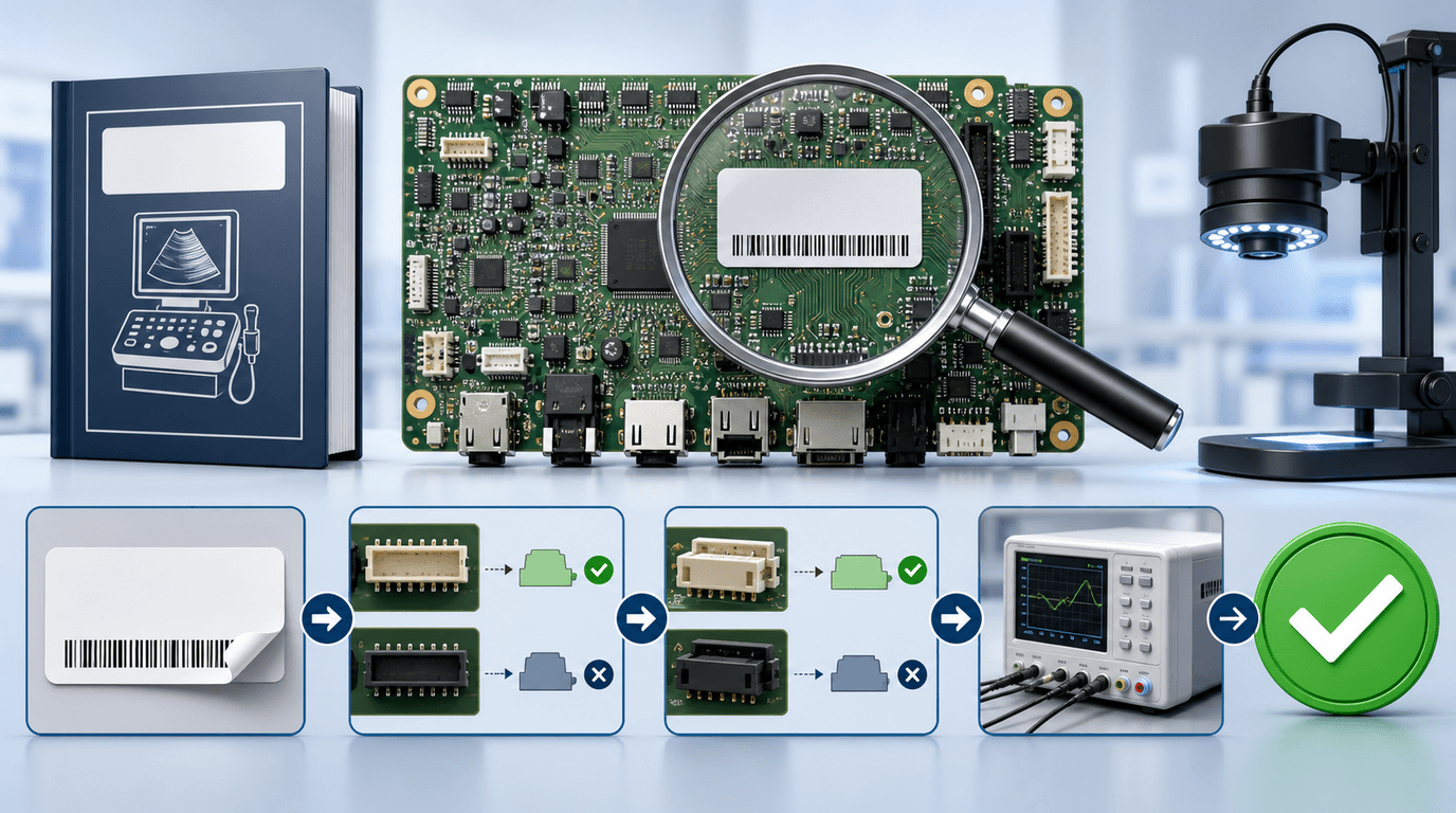
Verifying a medical ultrasound circuit board begins with decoding the physical identification labels attached to the assembly. Diagnostic ultrasound circuit boards feature multiple numbers printed or stickered across the PCB substrate, creating frequent confusion during parts identification.
Service technicians must understand the three distinct levels of board numbering:
- Bare PCB Silkscreen Number: Etched directly onto the green or blue fiberglass substrate during raw board manufacturing. This number identifies only the unpopulated circuit board layout and is often shared across multiple board generations. Never order replacement parts based solely on bare PCB silkscreen numbers.
- Top Assembly Part Number (P/N): Printed on a white barcode sticker affixed after component population and soldering. This is the authoritative assembly part number (e.g., GE PN 5729044-7 or Philips PN 453561279498) that defines the completed functional board.
- Hardware Revision Sub-Suffix (Rev): Indicated by a trailing letter or numerical extension (e.g., Rev A, Rev .P18, or Rev -8). The revision code specifies circuit modification levels, FPGA chip speeds, memory capacities, or component supplier updates.
To cross-check a received replacement board against your target ultrasound scanner, follow this three-point verification workflow:
- Point 1: OEM Service Manual Parts List Audit: Consult the official OEM service manual for the exact console model, system serial number prefix, and software version. Verify that the top assembly part number and revision letter match the allowable option list specified by the manufacturer.
- Point 2: Revision Compatibility Is Evidence-Based: A higher suffix is not automatically backward compatible, and a nearby model or base number is not proof of interchangeability. Verify both directions of any substitution in OEM documentation or a validated compatibility record for the exact hardware and software configuration.
- Point 3: Provenance & Anti-Counterfeit Verification: As highlighted in our ultrasound parts provenance and quality report, inspect barcode stickers under magnification to ensure labels have not been tampered with, altered, or re-pasted over harvested grey-market circuit boards.
What does a worked verification matrix look like across GE, Siemens, and Philips board part numbers?
To illustrate part-number verification in practice, the matrix below details real ground-truth board entries extracted from Rongtao Medical's verified catalog across major OEM platforms (GE HealthCare, Siemens Healthineers, Philips Healthcare) 6. Use these worked examples as reference templates when auditing incoming replacement parts:
| OEM Brand & Platform | Functional Board Category | Top Assembly Part Description | Verified OEM Part Number | Revision Code Format | Critical Compatibility Note |
|---|---|---|---|---|---|
| GE Voluson E8 | Transmit/Receive Processing | GE RFM323F Board Assembly | 5729044-7 | Rev .P18 | Match the complete label and confirm the installed hardware/software configuration. |
| GE Voluson E10 | High-Density Beamformer | GE RFM423F Board Assembly | KTZ304074-R / 5729200-8 | Rev -8 | Confirm whether both markings identify the same offered assembly and verify the E10 revision. |
| Siemens S2000 | Back-End Processing | Siemens S2000 BE Board | 7472421 | Rev OEM Standard | Capture the physical revision and validate it for the target S2000 configuration. |
| Siemens S2000 | Transmit/Receive Module | Siemens S2000 TR Board | 7475028 | Rev OEM Standard | Confirm the physical revision and follow the OEM incoming functional test. |
| Philips iU22 | Acquisition Interface | Philips iU22 AIM Board | 453561279498 | Rev Standard | Match the cart, hardware/software level and connector condition. |
| Philips EPIQ 7 | Acquisition Control | Philips EPIQ ACQ-A Board | 453561704246 | Rev Sub-Assy | Confirm the exact EPIQ generation, hardware suffix and software compatibility. |
Source: Rongtao Medical catalog identity records; all compatibility notes require OEM or validated cross-reference confirmation
Where do 510(k), UDI and the OEM service manual fit in part verification?
Part-number verification is primarily an engineering and quality-control task. Regulatory records provide context for the finished device, while OEM service information and validated configuration records govern internal-board matching.
When a health system modifies or repairs a diagnostic ultrasound system, maintaining the device's original cleared safety and performance specifications requires alignment across three regulatory reference points:
- FDA Configuration Context: Diagnostic ultrasound consoles and transducers appear under FDA product codes including IYO and ITX 2. For example, the Siemens ACUSON S2000 is associated with K072786 and the Philips CX50 with K081802. A circuit, firmware, output or intended-use change may require a servicing-versus-remanufacturing and regulatory assessment; do not assume that a third-party label alone determines the outcome.
- FDA Unique Device Identification (UDI) & AccessGUDID: UDI records identify finished devices and selected label attributes 1. They can help confirm brand/model identity but should not be used as proof that an internal board or revision is compatible.
- IEC 63077:2019 Refurbishment Practice Standard: International standard IEC 63077:2019 defines good refurbishment practices for medical imaging equipment, mandating that refurbished or repaired medical devices must meet the same essential performance and electrical safety requirements as when originally placed on the market 3.
This regulatory framework aligns directly with the supplier vetting protocols analyzed in our guide to qualifying an ultrasound parts and service supplier using FDA registration data.
What acceptance tests prove a repaired board is safe to return to clinical use?
To rigorously evaluate a repaired or replacement ultrasound board, biomedical engineering teams should execute a sequential 6-Gate Acceptance Testing Protocol before releasing the scanner to clinical service 45.
The six testing gates are structured as follows:
- Gate 1: Incoming Physical & ESD Inspection: Upon unboxing, verify anti-static ESD packaging integrity. Inspect the PCB for physical shipping damage, hairline solder cracks, damaged connector pins, or signs of liquid ingress. Confirm tamper-evident serial warranty seals are intact.
- Gate 2: Part Number & Revision Cross-Check: Verify barcode label top assembly PN and revision sub-suffix against the purchase order, packing slip, and OEM service manual parts list using Table 1 guidelines.
- Gate 3: Cold Boot & Diagnostics Self-Test: Install the board into the console card cage adhering to strict ESD grounding protocols. Perform a cold boot. Access the OEM diagnostic service menu and execute automated system self-tests (e.g., GE Service Desktop, Siemens Diagnostics, or Philips TechAdmin). Verify that all onboard voltage rails, FPGA bus checks, and memory tests pass with zero error codes.
- Gate 4: Reference Phantom Acoustic Image & Channel Check: Connect a calibrated reference transducer and image an acoustic tissue-mimicking phantom (such as a CIRS or ATS phantom). Evaluate 2D axial/lateral resolution, high-frequency penetration, color Doppler sensitivity, and channel uniformity. Verify that zero vertical acoustic lines or dropouts exist across the entire array.
- Gate 5: IEC 60601 Electrical Safety & Leakage Test: Using a calibrated medical safety analyzer (e.g., Fluke ESA620), measure chassis touch leakage current, earth leakage current, and patient lead applied-part leakage current in accordance with IEC 60601-1 and IEC 60601-2-37 standards 4. Confirm leakage currents remain well below maximum allowable thresholds (typically <100 µA for chassis leakage).
- Gate 6: 48-Hour Real-Machine Load & Thermal Soak: Leave the system powered on under continuous imaging stress mode for 48 hours inside a temperature-controlled room. Continuous thermal load testing exposes latent component degradation, drying capacitors, and thermal-expansion solder joints that bench testing fails to catch.
For further insights into thermal soak methodologies, consult our detailed analysis on ultrasound board failure patterns and thermal burn-in testing.
| Acceptance Gate | Evaluation Focus | Mandatory Testing Tool / Method | Pass Criteria | Disqualifying Failure Mode |
|---|---|---|---|---|
| Gate 1: Physical / ESD | Packaging & PCB Integrity | Visual inspection, ESD wrist strap | ESD shield sealed, zero pin bending, intact warranty seal | Torn ESD bag, bent connector pins, broken PCB corner |
| Gate 2: PN & Rev Match | Configuration Alignment | Silkscreen barcode vs. PO cross-check | Exact top assembly PN and compatible revision code | Incompatible rev sub-suffix, bare PCB number mismatch |
| Gate 3: Cold Boot / Self-Test | Electronic Bus & Voltage Rail | Console OEM diagnostic menu | 100% self-test pass rate, uncorrupted boot log | System boot loop, FPGA bus error code, status LED fail |
| Gate 4: Acoustic Phantom | Signal Processing & Channels | Reference phantom (CIRS/ATS), 2D/Doppler | Uniform channel acoustic gain, zero line dropouts | Vertical acoustic black lines, Doppler velocity noise |
| Gate 5: IEC 60601 Safety | Electrical Leakage Current | Calibrated medical safety analyzer | Chassis leakage <100 µA; patient leakage <10 µA | Ground open leakage spike, insulation breakdown |
| Gate 6: 48-Hour Load Soak | Thermal & Load Reliability | 48-hr continuous stress imaging mode | Zero thermal shutdown, stable image over 48 hours | Thermal reboot at hour 14, high-voltage drop under load |
Source: Rongtao Medical Quality Assurance Standard; IEC 60601-1 / IEC 63077 standards
What evidence should a board-repair vendor send back with the board?
Qualified ultrasound repair providers do not ship circuit boards in plain boxes without technical documentation. To satisfy ISO 13485 QMS traceability requirements and internal audit standards, hospital procurement teams should require board-repair vendors to supply a complete documentation package alongside every returned or advance-exchange board:
- Component Replacement & Root-Cause Work Order: A detailed report listing every micro-electronic component replaced during repair (e.g., switching transistors, high-voltage MUX ICs, decoupling capacitors) alongside root-cause failure analysis findings.
- 48-Hour Burn-In Temperature & Load Log: Time-stamped test logs documenting that the board completed a continuous 48-hour soak on an operational OEM test console prior to dispatch.
- Calibrated Electrical Safety Pass Certificate: Signed test sheet displaying measured chassis and patient leakage currents, referencing the serial number and calibration date of the safety analyzer used.
- Component Provenance Record: Supplier and lot traceability, incoming-inspection method, nonconformance disposition and evidence appropriate to the component risk; microscopy alone cannot certify authenticity.
- Tamper-Evident Warranty Seal: A serialized warranty sticker applied over board fastening screws, protecting both buyer and vendor under clear 90-day warranty terms.
Frequently Asked Questions (FAQ)
Q1: Can a different board revision work in my ultrasound scanner?
Answer: Only a model- and revision-specific compatibility record can answer that. Do not infer backward or forward compatibility from a higher suffix, similar PCB layout or seller description. Verify the top assembly number, hardware revision, console configuration and software level against OEM documentation or a validated cross-reference.
Q2: What is the difference between a bench power-on and a post-repair acceptance test?
Answer: A brief power-on is only one observation. A risk-based acceptance record adds identity, diagnostics, applicable functional or imaging checks, electrical safety where the repair affects it, and representative-load operation. Passing those gates supports release under the defined test scope; it cannot prove future reliability.
Q3: How do I look up a device identifier in AccessGUDID?
Answer: Search AccessGUDID using the Device Identifier from the label or by company and brand/model. DI formats vary by issuing agency. Treat the result as finished-device identity context, not an internal service-parts list.
Q4: Why add representative-load testing if the board passes OEM self-diagnostics?
Answer: A self-test is one evidence point and may not reproduce intermittent, workload- or temperature-dependent behavior. Rongtao's published service process uses a 48-hour real-machine test; the acceptance record should show the target chassis, workload, duration, interruptions and result rather than assume that time alone proves reliability.
Q5: What should I do if a received replacement board fails Gate 4 acoustic phantom testing?
Answer: Immediately re-verify probe integrity on a secondary machine to confirm the phantom dropout is not caused by the test transducer. If the probe is verified intact, document phantom image screen captures, freeze board installation, and initiate a Return Merchandise Authorization (RMA) with the vendor citing Gate 4 acoustic channel failure.
Where does Rongtao Medical fit — and where it does not?
To maintain complete operational and technical clarity, healthcare buyers should understand precisely how Rongtao Medical supports board verification and acceptance testing—and where our service boundaries lie.
Where Rongtao Medical Fits:
- ISO 13485:2016 Certified Quality System: Governed by accredited ISO 13485:2016 and ISO 9001:2015 quality management systems, enforcing complete component traceability and rigorous testing.
- In-House Test Infrastructure: Rongtao publishes a 3,000 m² facility, hundreds of systems/probes/test platforms and a 48-hour real-machine test for repaired boards. Confirm the target chassis, workload and acceptance record for the specific service.
- Confirm the Documentation Package: For the quoted service or part, specify the work-order report, applicable 48-hour real-machine record, functional or safety results, identity photos and warranty terms that will accompany shipment.
- Verified Part Catalog Ground Truth: Maintaining an extensive catalog of photo-backed, verified board part numbers and revisions across all major imaging brands.
Where Rongtao Medical Does NOT Fit:
- No OEM Affiliation: Rongtao Medical is an independent service, repair, and parts provider. We are not affiliated with GE HealthCare, Philips Healthcare, Siemens Healthineers, or Canon Medical. OEM brand names are cited solely for part compatibility and equipment identification.
- No Guarantee on Unverified Field Swaps: We cannot guarantee board compatibility if a customer orders a part without verifying top assembly part numbers and system software revisions against OEM service manuals.
- No Unqualified Servicing: We strongly advise that board installation and acceptance testing be performed exclusively by qualified biomedical engineers adhering to strict ESD and electrical safety protocols.
Quote-Ready Handoff: Preparing a Board Part Request
When requesting a replacement board or repair evaluation, precise identity and configuration data makes compatibility review and quote preparation more reliable. It does not guarantee a match until the supplier confirms the exact part, revision and system context in writing. Please provide:
- Console OEM, Model & Software Release: Target system details (e.g., GE Voluson E8 BT12, Philips EPIQ 7 1.5, or Siemens S2000 VB20).
- Top Assembly Part Number & Revision Code: Verbatim part number from barcode sticker (e.g., GE 5729044-7 Rev .P18 or Philips 453561279498).
- High-Resolution Photographs: Clear photos of barcode stickers, revision codes, and board substrate.
- Observed Failure Symptoms & Self-Test Log: Summary of clinical symptoms, diagnostic self-test pass/fail codes, and error messages.
- Service Type Requested: Specify board repair, advance exchange, or direct stock purchase.
To submit your board verification request to our engineering team, visit Rongtao Medical Quote & Technical Support Request or browse our verified part listings at Rongtao Multi-Brand Parts & Board Catalog.