
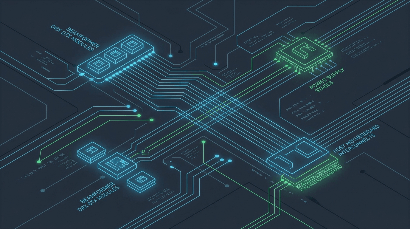
Introduction: Structured Board Isolation for GE Ultrasound Platforms
GE HealthCare diagnostic ultrasound consoles—ranging from women's health workhorses like the Voluson E8, E10, P8, and S6 to general imaging flagships like the LOGIQ E9, LOGIQ E10, and LOGIQ E11, alongside cardiovascular platforms like the Vivid E80, Vivid E90, and Vivid E95—represent one of the largest installed equipment bases in global healthcare. Built on FDA-registered device architectures and complex high-density beamforming hardware, these systems integrate multi-channel receiver arrays, high-current switching power supplies, and host processing engines.
However, when an internal circuit board fails, field service technicians and hospital biomedical equipment technicians (BMETs) face a complex diagnostic challenge. Symptoms such as complete power loss, acoustic line dropouts across all probes, system boot freezes, or unresponsive touch screens can originate from multiple interacting sub-systems. A field-replaceable-unit procedure may point to a larger assembly swap; an independent component-level route should be considered only when isolation, repairability and post-repair acceptance are documented.
For biomedical engineering departments, independent service providers, and medical equipment refurbishers, board-level component repair and targeted board replacement present a cost-effective, high-reliability alternative. By correlating physical hardware symptoms with specific board families, verified part numbers, and revision compatibility, technicians can isolate defects rapidly and restore equipment to factory specifications.
For sister diagnostic frameworks on other major multi-brand platforms, service teams can reference our decision paths for Philips iU22/EPIQ board symptom isolation and Siemens Acuson S2000/Sequoia board symptom isolation, alongside our field guide to how GE ultrasound boards fail.
Which GE board family does my symptom point to (Voluson E8/E10, LOGIQ E9/E10/E11, Vivid E95)?
Before removing chassis covers or ordering replacement parts, service engineers should classify observed console behavior into one of three primary hardware symptom families: (1) Image Path & Transmit/Receive Front-End, (2) Power Conversion & Management Chain, or (3) Host Control, System Motherboard, and User Interface Subsystem.
Electronic circuit failures on GE ultrasound consoles follow predictable physical failure mechanisms: high-voltage transmit pulsers and beamformers experience thermal fatigue and fast-switching semiconductor degradation; main power supplies suffer electrolytic capacitor breakdown under continuous operational load; and control panel assemblies experience mechanical micro-switch wear and interconnect ribbon oxidation.
Table 1 maps observed hardware symptoms across GE Voluson, LOGIQ, and Vivid console families directly to suspected functional sub-systems, primary candidate board assemblies, and verified manufacturer part numbers from Rongtao Medical's verified catalog 5:
| GE Console Platform | Observed Hardware / Clinical Symptom | Suspected Functional Sub-System | Primary Candidate Board Assembly | Verified OEM Part Number |
|---|---|---|---|---|
| Voluson E8 / E10 | Vertical black acoustic dropouts across all array probes; no echo signal | High-Voltage Acquisition / Beamformer | RFM / DRX Beamformer Module | DRX5 5301040-5 / DRX6 5301160-6 |
| Voluson E8 / E10 | B-mode noise elevation; RF signal distortion across transmitter channels | Front-End Transmit/Receive Drive | GTX / TX64 Transmit Driver Board | GTX2.4 5201044-3 / GTX2.5 5201044-7 |
| Voluson E8 / E10 | CW Doppler mode noise floor spike; audio signal distortion | Continuous Wave Processing | MRX-CW Processing Board | MRX CW 5393908 |
| Voluson E8 / LOGIQ E9 | High-density matrix probe initialization failure; TR channel error | High-Density Beamforming Array | ETX128 High-Density Beamformer | ETX128 5321216-4 / TX64 5436388 |
| Voluson E8 / S6 / P8 | Complete power deadness; power LED dark; main AC breaker trips | Main AC/DC Power Conversion | Main Power Supply Unit (PSU) | PSU 5205052-10 / 5205052-3 |
| LOGIQ E9 / E10 | System shuts down abruptly during high-power Color Doppler scan | DC High-Voltage Regulation | LOGIQ E9 High-Power PSU Module | PSU 5433408-21 / GA200876 |
| Voluson E8 / LOGIQ E9 | Small form-factor auxiliary power failure; standby voltage drop | Auxiliary Low-Voltage DC Rail | BEP Small Power Supply Module | BEP Power 5393801 |
| Voluson E8 / LOGIQ E9 | System hangs during GE boot logo splash; PCI communication error | Host PC System Control | System Control Motherboard / PC Board | AIMB-563 5155024 / PC 5380000-2 |
| Voluson E8 BT12/BT13 | System initialization freeze; configuration load failure | System Master Controller | SYSCONML Master Board / PC Motherboard | SYSCONML 5252250-3 / PC 5823770-2 |
| LOGIQ E9 / E10 | Trackball movement frozen; mode rotary knobs unresponsive | Operator User Interface Control | Main Control Panel Board Assembly | Control Panel 5207000-42 |
| LOGIQ E9 / E10 / Voluson E10 | Touch screen display unresponsive to touch inputs; glass intact | Touch Screen Digitizer Controller | Touch Screen Assembly / Controller | Touch 5207000-23 / 5776094 |
| Vivid E95 / E80 / E90 | Secondary display video flickering; main monitor signal loss | Digital Video Interface Processing | IO Video Interface Board | IO Video 9-1301-3707 / 5776030-S |
| Vivid E95 | General gain encoder drift; mode switch intermittent response | Control Panel Encoder Subassembly | Control Panel Encoder Assembly | Encoder S5718726-2 / TAS4719N |
Source: Rongtao Medical technical case database; GE Healthcare service manual specifications; tested parts inventory
How do I tell a probe fault from a GE console front-end or beamformer fault?
One of the most frequent diagnostic errors in ultrasound service is misdiagnosing a damaged transducer array or cracked cable assembly as an internal console beamformer defect—or conversely, swapping high-cost acquisition boards when the true root cause is a single failed probe channel.
On high-channel GE platforms like the Voluson E8/E10 or Vivid E95, vertical black acoustic dropouts or elevated B-mode noise can originate from broken piezoelectric crystals in a RAB6-D or C1-5-D probe, bent connector pins on the probe receptacle, or shorted transmit pulsers on a GTX2.4 (PN 5201044-3) or DRX5 (PN 5301040-5) beamformer board 3.
To conclusively isolate probe defects from console front-end failures before requesting parts, field service technicians should follow this four-step diagnostic gate:
- Cross-Console Transducer Swap: Where the probe is documented compatible, compare it on a known-good console and compare a known-good probe on the suspect console using the same preset. A defect that follows the probe strongly implicates the probe path; a clean second-console result shifts attention to the primary console. Confirm connector, port, preset and channel evidence before naming the failed assembly.
- Multi-Port Receptacle Shift: On consoles equipped with multi-port probe selection boxes, move the suspected probe from Port 1 to Port 2 and Port 3. If the dropout disappears on Port 2, the defect is localized to Port 1's pin-receiver connector block or selection relay board, rather than the main DRX/GTX beamformer module.
- Artifact Geometry & Depth Analysis: Inspect the physical geometry of the visual defect. True console beamformer or transmit/receive channel dropouts produce razor-sharp, perfectly vertical dark lines extending from the array apex straight to the bottom of the display monitor at fixed column coordinates, invariant to gain or focal zone shifts. Probe element decay typically produces soft-edged acoustic shadows that widen with depth and change position when flexing the probe strain relief.
- In-Air Reverberation Uniformity Test: Hold the un-coupled transducer in air at maximum 2D gain. A healthy console front-end produces uniform, horizontal reverberation bands across the entire field of view. A dead transmit/receive channel on a DRX or GTX board produces a continuous vertical blanking line cutting through all horizontal reverberation bands.
For additional guidance on verifying replacement board part numbers after isolating a console fault, see our technical report on verifying ultrasound board part numbers and post-repair acceptance testing.
Is a no-boot or power-drop GE console a PSU, RSX, init or motherboard fault?
A 'no-boot', 'spontaneous power-off', or 'unplanned reboot loop' condition on a GE console can involve the main supply, power management, a downstream load, cooling, the host computer, storage or initialization control. The symptom narrows the next evidence to collect; it does not identify a failed board by itself.
Qualified service technicians should record physical indicators, logs and repeatable workload correlation, then follow the exact model/revision service flow. Any energized measurements belong to OEM-qualified procedures. Four useful evidence paths are:
- Path 1: Complete Power Deadness: Verify approved external power and cord checks first. The inlet/protection path, main supply and downstream shorts remain candidates. Do not infer that catalog PNs 5205052-10 or 5433408-21 fit the installed console until the physical label and revision are matched.
- Path 2: Brief Power Activity Followed by Shutdown: Record protection indicators and codes. A supply, sequencing fault or overloaded downstream assembly may produce this presentation; never bypass a protection circuit or disconnect internal loads outside the OEM isolation procedure.
- Path 3: Power Indicators Stable, Boot Does Not Complete: Collect boot stage, diagnostic LEDs and logs. Host, storage, controller, display and power-good sequencing are competing hypotheses; visible fan activity is not proof that every power output is healthy.
- Path 4: Reset During a Repeatable Scan Workload: Record the exact mode, probe, elapsed time and thermal condition. Power delivery is one candidate alongside cooling, transmit-path and software-controlled protection; assign root cause only after controlled reproduction and model-specific testing.
Service engineers evaluating whether to repair a failing power module or replace the board outright can consult our comprehensive guide on ultrasound board repair vs replacement decision frameworks.
What does Rongtao's 16-case GE repair archive reveal about board rework success?
To evaluate the practical repairability of GE ultrasound circuit boards, we analyzed Rongtao Medical's documented 16-case GE board repair dataset, spanning Voluson E8 (8 cases), Voluson E10 (4 cases), Voluson P8 (1 case), Voluson S6 (1 case), and Vivid E95 (2 cases) 4.
Table 2 details the distribution of board families, specific fault mechanisms, and repair resolution methods across the 16 documented cases:
| GE Console Model | Board Assembly Identified | Observed Failure Symptom | Root Cause / Diagnostic Finding | Repair Resolution Method | Outcome Category |
|---|---|---|---|---|---|
| Voluson E10 | RFM (Radio-Frequency Module) | B-mode image anomaly across all probes | Bench-isolated to the RFM beamformer front-end | Replaced failing front-end ICs; full channel map recalibrated | Component Rework (Saved) |
| Voluson E8 | Probe interface / front-end | No echo signal; system reports a phantom (virtual) probe | Probe-detect circuit and front-end channel relay at fault | Repaired probe-port detection circuit; replaced front-end relay | Component Rework (Saved) |
| Voluson E8 | Motherboard | System freezes during scanning sessions | Thermal stress testing implicated the motherboard chipset | Chipset reflow + power-management IC replacement | Component Rework (Saved) |
| Voluson E8 | TX/RX board (transmit / receive) | Image lacks clarity, low contrast across modes | Degraded TX/RX channel group identified on bench | TX/RX channel-network rework; gain recalibrated vs reference phantom | Component Rework (Saved) |
| Voluson E8 | System / control board | System hangs before reaching the scanning interface | System-board ESD strike plus a corrupt boot ROM | Boot ROM reflash + ESD damage repair | Component Rework (Saved) |
| Voluson E8 | Touch screen + control panel | Touch screen unresponsive, no display output | Touch-panel controller and internal ribbon at fault | Touch controller replaced, panel ribbon rebuilt, backlight rail repaired | Component Rework (Saved) |
| Voluson P8 | DBM64 digital beamformer (64-channel) | Image anomaly after warm-up (thermal-dependent failure) | Thermal cycling reproduced the fault on the DBM64 | Solder-joint reflow on suspect channels + thermal-paste refresh | Component Rework (Saved) |
| Voluson E8 | Hardware init / configuration | Auto-reboot loop; hardware initialization and configuration failure | Multi-board triage across power, motherboard and init chain | Front-end voltage rails rebuilt; configuration EEPROM reflashed | Component Rework (Saved) |
| Voluson E10 | RFM (Radio-Frequency Module) | Boot-time error; cannot enter scanning mode | RFM fault confirmed via diagnostic logs | Module rebuilt and bench-tested; full boot sequence restored | Component Rework (Saved) |
| Voluson E10 | RFM423 (Radio-Frequency Module) | All probes return no echo on startup | RFM423 channel fault isolated on bench | RFM423 channel rework; element-by-element calibration | Component Rework (Saved) |
| Voluson E10 | Main power supply | Power drop on boot; system fails to reach the OS | Failing PSU rails (bulk capacitors + control IC) | PSU rail rebuild + capacitor refresh; 48-hour live-system burn-in | Component Rework (Saved) |
| Voluson E8 | RSX (power management) | Boot-time power-management error reported | RSX sequencing IC and rail monitor at fault | RSX rebuild — sequencing IC and rail monitor replaced | Component Rework (Saved) |
| Voluson E8 | Main power supply | System will not power on | Failed bulk electrolytic capacitors | PSU rebuild — primary rail caps + control IC replaced | Component Rework (Saved) |
| Voluson S6 | Control panel | Knobs unresponsive on the operator console | Worn encoder in the operator panel | Encoder bank replaced, ribbon refit, panel firmware re-paired | Subassembly Swap (Saved) |
| Vivid E95 | Front-end / TR board | Flicker artefact in the echo region | Isolated to the front-end TR stage | Front-end channel rework; ground-plane decoupling rebuilt | Component Rework (Saved) |
| Vivid E95 | Display / video subsystem | Display flickers from boot | Video interface board fault | Video interface board replaced, EDID renegotiated | Board Replacement |
Source: Rongtao Medical technical repair log and engineering case archive
Three key takeaways emerge from this empirical 16-case GE dataset:
- High Board Retention Rate: 15 of 16 documented faults were resolved while retaining the original board assembly — 14 through component-level rework (chipset reflow, channel-network rework, power-rail and capacitor rebuild, EEPROM/boot-ROM reflash) and one through an encoder subassembly swap. A single case, a Vivid E95 display/video interface board, required board replacement.
- Recurring Failure Patterns: Across the 16 cases, faults concentrated in three areas: the image-path / beamformer front-end (RFM, probe interface, TX/RX, DBM64, front-end/TR), the power and power-management rails (main PSU, RSX), and the host control / init chain (motherboard, system-control board, hardware-init configuration). Touch-screen and control-panel encoder faults made up the remainder.
- Safe Escalation Boundaries: Component-level rework is viable when the board substrate and traces remain intact and replacement components are available. When a board suffers catastrophic physical damage or an un-sourceable proprietary-component failure, full board replacement becomes the practical route.
What GE board part numbers are available in tested stock, and why does revision matter?
When ordering a replacement GE circuit board or scheduling an advance exchange, service engineers must verify both the base manufacturer part number and the hardware revision suffix. GE Healthcare consoles frequently undergo hardware block updates (BT updates, e.g., Voluson E8 BT08 vs BT12 vs BT13, or LOGIQ E9 Rev R1 vs R5) that modify board pinouts, voltage requirements, or FPGA firmware compatibility.
Rongtao Medical maintains 111 photo-backed GE Healthcare part SKUs in verified stock 5. Table 3 lists high-demand verified GE board part numbers across key functional categories:
| Board Functional Category | Board Description / Module Name | Verified GE OEM Part Number | Compatible GE Console Models |
|---|---|---|---|
| Acquisition / Beamformer | DRX5 Beamformer Board Assembly | 5301040-5 | Voluson E8 (BT08–BT12) |
| Acquisition / Beamformer | DRX6 Beamformer Module Assembly | 5301160-6 | Voluson E8 / Voluson E10 |
| Acquisition / Beamformer | GTX2.4 Transmit Driver Board | 5201044-3 | Voluson E8 / LOGIQ E9 |
| Acquisition / Beamformer | GTX2.5 Transmit Driver Board | 5201044-7 | Voluson E8 / Voluson E10 |
| Acquisition / Beamformer | MRX Continuous Wave Processing Board | 5393908 | Voluson E8 / Voluson E10 |
| Acquisition / Beamformer | TX64 Transmit Board Assembly | 5436388 | LOGIQ E9 / LOGIQ E10 |
| Acquisition / Beamformer | ETX128 High-Density Beamformer | 5321216-4 | LOGIQ E9 / LOGIQ E11 |
| Power Supply / Regulation | Voluson Main AC/DC Power Supply | 5205052-10 / 5205052-3 | Voluson E8 / Voluson E6 |
| Power Supply / Regulation | LOGIQ E9 High-Power PSU Module | 5433408-21 / GA200876 | LOGIQ E9 (All Revs) |
| Power Supply / Regulation | BEP Small Form Power Supply Unit | 5393801 | Voluson E8 / LOGIQ E9 |
| Motherboard / Host Control | AIMB-563 Host PC Motherboard | 5155024 | Voluson E8 (BT08–BT10) |
| Motherboard / Host Control | PC System Board Assembly | 5380000-2 | Voluson E8 / LOGIQ E9 |
| Motherboard / Host Control | PC Motherboard Assembly | 5823770-2 | Voluson E8 BT13 / E10 |
| Motherboard / Host Control | SYSCONML Master Controller Board | 5252250-3 | Voluson E8 (BT10–BT13) |
| UI / Display Subsystem | Operator Control Panel Assembly | 5207000-42 | LOGIQ E9 / LOGIQ E10 |
| UI / Display Subsystem | Touch Screen Assembly & Controller | 5207000-23 / 5776094 | LOGIQ E9 / Voluson E10 |
| UI / Display Subsystem | IO Video Interface Board | 9-1301-3707 | Vivid E95 / Vivid E90 |
| UI / Display Subsystem | Control Panel Main Board | 5776030-S | Vivid E95 / Vivid E80 |
Source: Rongtao Medical parts engineering catalog
Laptop LOGIQ e tickets for catalog TX64 5436388, leftover 2404903 / Shop 5436388-S, and catalog battery 5451284-2 belong on the GE LOGIQ e versus LOGIQ E9 board path. The TX64 5436388 row in the table above is a leftover E9/E10 label, not a cart-swap license.
Where does Rongtao's GE support start and stop — and what should I send for a quote?
Rongtao Medical operates as a specialized independent service organization and parts provider, delivering board-level repair, advance board exchanges, and tested replacement parts for GE Healthcare ultrasound systems worldwide. In compliance with FDA medical device servicing guidelines 1, Rongtao's board servicing restores circuit assemblies to original manufacturer specifications without altering intended clinical design or device classification.
Rongtao's public catalog dataset contains 111 photo-backed GE part records 5, and the company publishes 35+ senior engineers, a standard 5-to-8-business-day repair turnaround, 48-hour real-machine testing for repaired boards and a typical 90-day warranty 6. For replacement stock, confirm the exact unit, condition, test scope, live availability and warranty in the quote.
To explore verified GE parts inventory, visit our dedicated GE Healthcare ultrasound board and parts catalog page or contact our technical engineering team via Rongtao Medical contact engineering.
When requesting a GE board repair or parts quote, please provide: (1) Exact GE console model and system software version (e.g., Voluson E8 BT12, LOGIQ E9 Rev R5), (2) Manufacturer board part number and revision suffix (e.g., DRX5 5301040-5 or Main PSU 5205052-10), (3) Clear photographs of both sides of the board and OEM barcode labels, (4) Specific observed hardware symptoms or diagnostic error logs, (5) Quantity required, and (6) Shipping destination for accurate freight turnaround.— Rongtao Medical Repair Handoff Protocol