
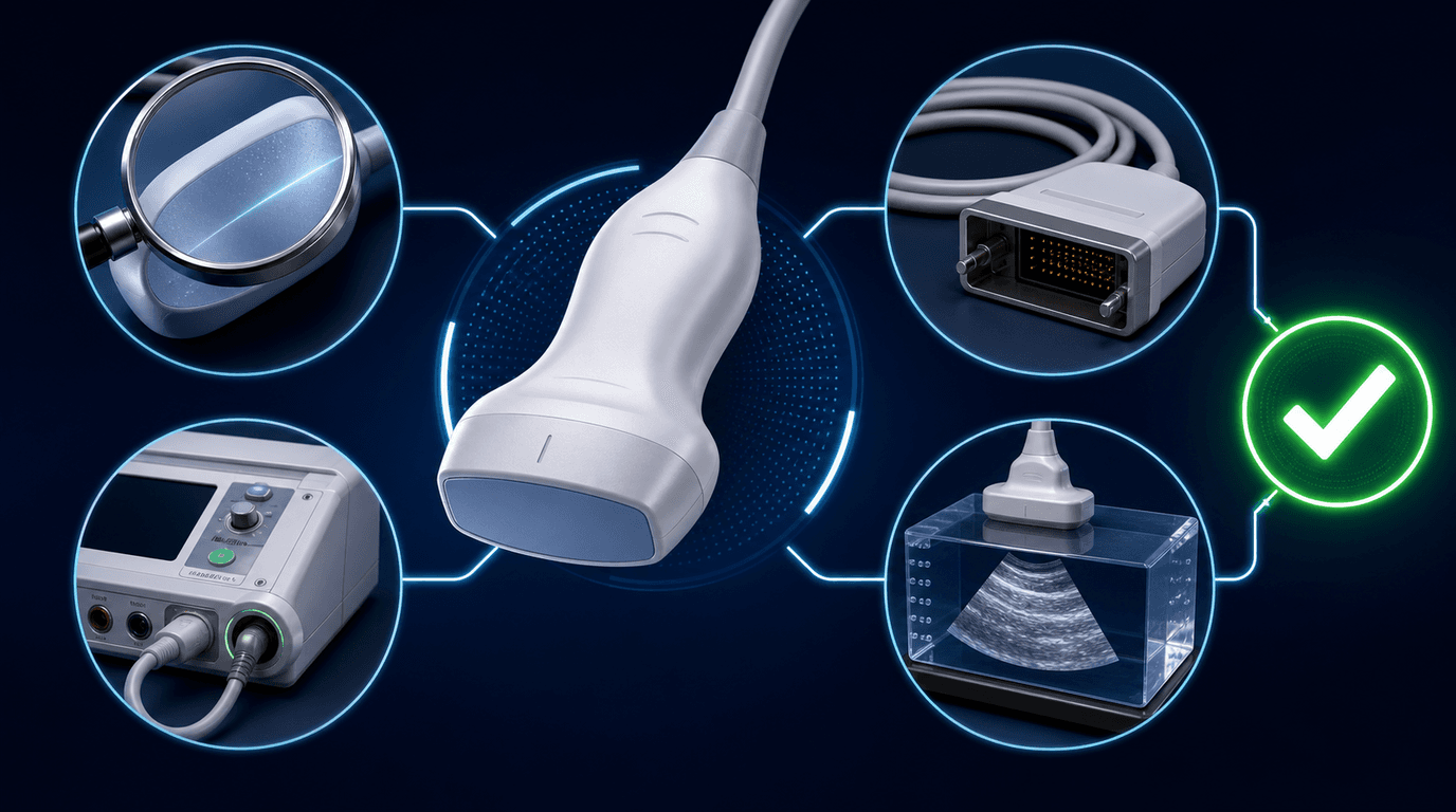
Introduction: Why Bench Power-On Is Not an Acceptance Protocol
When a repaired or pre-owned ultrasound transducer arrives at a hospital biomedical engineering department, Independent Service Organization (ISO), or outpatient imaging clinic, the immediate operational pressure is to plug it into a console, verify that a 2D image appears, and return it to clinical service. However, relying on a simple bench power-on check leaves clinical facilities exposed to grave electrical safety hazards, infection control breaches, and diagnostic misreadings.
Ultrasound probes are intimate patient-contact medical devices. Transesophageal echocardiography (TEE), endocavitory, intraoperative, and surface probes contact mucous membranes, bodily fluids, or disrupted skin. A probe with an intact acoustic lens but micro-fractured cable insulation can conduct dangerous patient enclosure leakage currents under fault conditions 2. Similarly, subtle crystal element dropouts might be invisible during an uncalibrated scan of a technician's forearm, yet obscure a deep vein thrombosis or small renal mass during clinical scanning.
To establish a rigorous quality and safety protocol, healthcare biomedical teams must enforce a structured incoming inspection and post-repair acceptance workflow. For complementary guidance on board-level acceptance testing, see our protocol on ultrasound board part-number verification and acceptance testing.
Anatomy of an Ultrasound Transducer: Stress Zones and Failure Modes
Understanding why transducers require multi-gated testing requires examining the complex physical architecture of modern ultrasound probes. A high-density diagnostic transducer—whether a 192-element linear array, a 128-element convex array, or a 2,000+ matrix array (such as xMATRIX or 4D volume probes)—integrates five distinct engineering layers within a tight hand-held enclosure:
- 1. Acoustic Lens & Matching Layers: The silicone or polyurethane outer acoustic lens protects internal components while matching acoustic impedance between piezoelectric crystals (~30 MRayls) and human tissue (~1.5 MRayls). Chemical exposure to high-level disinfectants (HLD), enzymatic cleaners, or non-approved wiping wipes causes lens swelling, edge debonding, and pinhole cuts.
- 2. Piezoelectric Array (PZT / Single Crystal): Lead zirconate titanate (PZT) ceramic or single-crystal (PMN-PT) elements convert high-voltage electrical pulses into high-frequency mechanical sound waves. Physical drops, thermal shock, or acoustic backing delamination crack these delicate crystals, resulting in dead channels.
- 3. Micro-Coaxial Cable Assembly: A typical 192-element array utilizes 192 individual micro-coaxial wires bundled inside a flexible shield jacket. Continuous bending at the strain relief causes conductor metal fatigue, short circuits between adjacent wires, and intermittent channel dropouts when flexing the cable.
- 4. Strain Relief & Housing Shell: The molded rubber strain relief relieves mechanical stress at the probe handle and connector housing junctions. Disinfection chemical degradation hardens rubber strain reliefs, causing cracks that allow fluid ingress into internal wiring.
- 5. Connector Assembly & Pin Receiver: Gold-plated contact pins engage the console's transducer interface (TI) board. Bent pins, pushed-back contacts, or fluid corrosion prevent electrical signal transmission, mimicking console front-end board failures.
What are the acceptance gates for a repaired or replacement probe?
A defensible transducer acceptance protocol uses three sequential gates. A failed safety gate stops clinical release and places the probe in quarantine; disposition may be reinspection, rework, return or replacement according to the facility procedure and supplier agreement.
- Gate 1: Physical Integrity & OEM IFU Reprocessing Audit: Inspect the physical housing for cracks, seam gaps, or missing screws. Examine the acoustic lens for pinhole cuts, chemical swelling, delamination, or edge lifting. Inspect the strain relief for tearing, cable jacket for cuts/discoloration, and connector assembly for bent, corroded, or missing gold contact pins. Verify that the probe model matches the facility's approved reprocessing Instructions for Use (IFU) for high-level disinfection (HLD) or sterilization.
- Gate 2: Electrical Safety & Enclosure Leakage Check (IEC 60601-2-37): Measure electrical chassis and patient enclosure leakage currents using a calibrated medical device safety analyzer and fluid bath immersion test setup. Confirm that patient leakage currents under normal and single-fault conditions fall strictly within IEC 60601-1 and IEC 60601-2-37 limits 2.
- Gate 3: Functional Image Quality & Acoustic Performance: Perform a two-stage image quality evaluation consisting of an in-air reverberation patterns test to detect crystal element dropouts 1, followed by a calibrated tissue-equivalent phantom scan (NEMA UD-2/UD-3 practice) 3 to evaluate penetration depth, axial/lateral resolution, spatial uniformity, and geometric accuracy.
This sequence is summarized below. Numeric limits must come from the exact probe IFU, connected-system classification, applicable standard edition and the facility's validated QA baseline; the table does not invent universal thresholds.
| Acceptance Gate | Test Parameter / Inspection Domain | Reference Standard / Tooling | Acceptance Criterion | Action Upon Failure (Reject Criteria) |
|---|---|---|---|---|
| Gate 1: Physical Integrity | Acoustic Lens Surface Condition | Visual 10x magnification, tactile feel | Zero cuts, tears, swelling, or delamination | REJECT: Return for lens replacement |
| Gate 1: Physical Integrity | Cable & Strain Relief Housing | Visual & flex test | Zero jacket cuts, exposed shielding, or strain tears | REJECT: Return for re-cable / strain repair |
| Gate 1: Physical Integrity | Connector & Pin Array | Visual pin audit & latch mechanism check | Zero bent, pushed back, or corroded pins; smooth latch | REJECT: Pin repair / connector rebuild required |
| Gate 2: Electrical Safety | Patient Enclosure Leakage Current | IEC 60601-2-37 / Safety Analyzer + Saline Bath | Pass the limit and test configuration applicable to the probe, connected system, applied-part classification and required conditions | QUARANTINE: Do not release clinically; document result and investigate or return |
| Gate 3: In-Air Reverberation | Crystal Element Dropout & Dead Lines | Console B-mode in-air high gain scan (PMID 30940416) | No new or clinically significant non-uniformity versus the validated baseline; confirm suspected dropout by a second method | QUARANTINE: Confirm on phantom or probe tester and assess clinical significance |
| Gate 3: Phantom QA | Maximum Depth of Penetration (DoP) | Tissue-Equivalent Phantom (NEMA UD-2/UD-3) | Within the facility's documented baseline tolerance using identical presets, phantom and measurement method | QUARANTINE: Repeat the controlled test and investigate probe/system contribution |
| Gate 3: Phantom QA | Axial & Lateral Pin Resolution | Tissue-Equivalent Phantom vertical/horiz. pins | Pins clearly resolved at target focal depths | REJECT: Array de-focusing / matching layer fail |
| Gate 3: Phantom QA | Caliper Distance & Geometric Accuracy | Phantom target distance measurements | Within the OEM or facility QA tolerance, including phantom and caliper uncertainty | QUARANTINE: Repeat and isolate console, preset, probe and phantom effects |
Source: Synthesis of IEC 60601-2-37, NEMA UD-2/UD-3, AAPM Report 74, AIUM statements, and Bigelow et al. (PMID 30940416)
Specialized Inspection Protocols for Transesophageal (TEE) and Endocavitory Probes
Transesophageal echocardiography (TEE) probes (such as the GE 6VT-D, Philips X7-2t, or Siemens Z6Ms) and 3D endocavitory transducers present unique clinical risks that require additional specialized acceptance steps beyond standard surface probes.
For TEE probes, Gate 1 should include the shaft, distal tip, articulation controls, bite-guard region, cable and connector. Exercise articulation only through the range and method specified in the exact OEM IFU; do not transfer generic angle limits between models. Quarantine any binding, sheath damage, fluid-ingress evidence or other condition that prevents validated cleaning and disinfection.
TEE electrical-integrity testing must follow the probe manufacturer's IFU and the instructions for the specified leakage tester or analyzer. Immersion boundary, test solution, adapters, connected equipment, test voltage and pass limit are model- and method-specific; an improvised full-shaft bath can damage the probe or invalidate the result. Any failed or ambiguous result is a clinical-release hard stop.
Acoustic Output, Thermal Index (TI), and Mechanical Index (MI) Compliance
Under IEC 60601-2-37, diagnostic ultrasound systems display real-time bio-effect safety indices: Thermal Index (TI, measuring potential tissue heating) and Mechanical Index (MI, measuring potential cavitation risk) 2.
During functional acceptance, confirm that the system recognizes the exact probe and displays the required output indices in supported modes without errors. The displayed TI/MI is not, by itself, an independent acoustic-output measurement. If a repair could affect the acoustic stack or output, route the probe through the OEM or a qualified acoustic laboratory's model-specific requalification method rather than applying a generic index ceiling or field hydrophone procedure.
Color Flow, Pulsed-Wave (PW) Doppler, and Spectral Calibration Acceptance
Comprehensive Gate 3 acceptance testing must extend beyond static 2D B-mode imaging to evaluate Doppler acoustic performance. Color Flow Mapping (CFM), Power Doppler, and Pulsed-Wave (PW) Spectral Doppler modes utilize distinct high-voltage pulse sequences that place extra stress on transducer crystal arrays and front-end beamforming channels.
When evaluating Doppler performance on a flow phantom (such as a Doppler string phantom or fluid-flow phantom), clinical engineers must verify three Doppler parameters:
- 1. Color Flow Sensitivity & Gate Registration: Verify that Color Doppler signals completely fill the lumen of a simulated blood vessel without bleeding into surrounding tissue structures or creating artificial noise flash. Misaligned crystal elements cause phase errors that corrupt velocity estimation.
- 2. Spectral Doppler Velocity Check: Use a validated flow phantom and repeatable geometry. Compare measured velocity with the phantom reference and the facility's documented tolerance, including angle and flow uncertainty.
- 3. Doppler-Mode Stability: Exercise representative supported PRF and Doppler settings within the QA procedure. Record cross-talk, ghosting, dropout or system errors; maximum-output stress testing requires a qualified laboratory protocol.
How does the in-air reverberation patterns test catch element dropout?
Detecting individual dead or degraded piezoelectric crystal elements in a linear, convex, or phased array transducer without expensive specialized hydrophone equipment (like FirstCall) historically presented a major challenge for field engineers. In 2018, published peer-reviewed research by Bigelow et al. (PubMed PMID 30940416) validated the diagnostic precision of the In-Air Reverberation Patterns Test 1.
The in-air reverberation test uses the large acoustic-impedance mismatch at the probe-to-air boundary to create a repeatable reverberation pattern. The pattern should be compared with a known-good baseline using the same console, preset, orientation and display settings; geometry and appearance vary by probe type.
A new localized non-uniformity can indicate an element, cable, connector or console-channel problem. The in-air image does not, by itself, distinguish those causes, so suspected dropout should be confirmed with a known-good probe or console, phantom imaging, or a validated probe tester.
Depending on array geometry and processing, dropout may appear as a vertical or sector-shaped loss of uniformity. Do not claim single-element counts from display shadows unless the method has been validated for that probe and console; save images and confirm with a second test.
What electrical-safety leakage must pass before a probe touches a patient?
Electrical safety is the non-negotiable cornerstone of transducer acceptance. Under IEC 60601-2-37 (the particular safety standard for ultrasonic diagnostic equipment) 2, transducers are classified as Applied Parts (Type BF or Type CF depending on clinical application).
The probe's insulation system separates internal circuitry from the patient. Chemical exposure, flexing, impact or fluid ingress can damage that protection, which is why visual inspection cannot replace the OEM-specified electrical-integrity test.
An objective Gate 2 record should document:
- The exact probe, connected system or approved adapter, applied-part classification and OEM test procedure used.
- The specified tester, accessories, solution or immersion boundary where applicable, calibration status and required test conditions.
- The limit taken from the applicable OEM/IEC procedure and the measured result for each required condition—without mixing console leakage limits with probe-insulation tests.
- A clear pass, fail or indeterminate disposition. Failed or indeterminate probes remain quarantined from clinical use pending qualified investigation.
Tissue-Equivalent Phantom Calibration & Image QA Parameters
Gate 3 acoustic performance evaluation requires scanning a calibrated tissue-equivalent phantom (such as a CIRS Model 040G or Gammex 403GS) manufactured to NEMA UD-2 and UD-3 standards 3. The tissue phantom provides background attenuation (~0.5 or 0.7 dB/cm/MHz) and contains embedded monofilament nylon target pins and hyperechoic/hypoechoic cystic structures.
Technicians must record five key quantitative performance baseline measurements during incoming acceptance:
- 1. Maximum Depth of Penetration (DoP): Use the same console, preset, output, gain, phantom, orientation and environmental conditions as the validated baseline. Compare the measured change with the facility's repeatability and action threshold; do not infer a probe root cause from DoP alone.
- 2. Axial & Lateral Resolution: Measure the minimum distance between closely spaced vertical and horizontal pin targets. Axial resolution reflects acoustic pulse length; lateral resolution reflects beamformer focusing performance.
- 3. Dead Zone Depth: Measure the distance from the lens surface to the first readable target pin. An enlarged dead zone indicates acoustic lens delamination or matching layer debonding.
- 4. Functional Focal Zone Uniformity: Scan horizontal pin groups across multiple focal zone settings. Verify that beam focusing remains sharp and symmetrical across all array segments.
- 5. Distance Caliper Accuracy: Measure certified phantom targets and compare results with the OEM or facility tolerance while accounting for phantom sound-speed and caliper uncertainty.
openFDA ITX recall surveillance: What the historical data reveals
To evaluate real-world field failure mechanisms that lead to regulatory intervention, we analyzed historical medical device recall records from the openFDA database 5.
The reviewed openFDA snapshot contained 147 recall actions under Product Code ITX. Recall data is event- and action-based passive regulatory information: it cannot establish failure incidence, comparative brand reliability, root-cause frequency or the probability that a received probe has a defect. The narratives are useful only as qualitative prompts for acceptance controls:
- Reprocessing, Sterility & Contaminated Gel (the largest group): Recalls for compromised package sterility, disinfectant-chemistry incompatibility, lens swelling, fluid ingress, and bacterial contamination of ultrasound gel — a reminder that acceptance must verify the reprocessing IFU for the exact probe model.
- Transducer Useful-Life, Labeling & Software (the other large group): Recalls in which transducers were returned to service beyond their defined useful life, plus mis-programmed (for example, certain TEE) transducers and labeling or 510(k) coverage gaps — directly relevant to accepting a repaired or pre-owned probe.
- Electrical & Battery Safety: A smaller set of recalls involve battery failure or smoke, degraded insulation, and potential enclosure leakage — precisely the defects the Gate 2 leakage check is designed to catch.
- Acoustic, Image & Mechanical Integrity: Another smaller set involve attenuated acoustic signal, chassis or edge-bonding separation, lens or housing cracks, and connector or strain-relief defects — the defects the physical and in-air reverberation gates catch.
These recall narratives illustrate categories an acceptance plan should consider, but they do not measure how often each category occurs. Clinical release still depends on the exact probe's IFU, inspection, electrical-integrity result and functional baseline.
For additional insights on evaluating repair quality before purchasing, consult our guide on ultrasound probe repair versus replacement failure data.
When must I reject a probe and return it for rework?
Predefined quarantine criteria prevent subjective release decisions. A quarantined probe is not returned to clinical use until the failed or indeterminate condition is resolved under the facility procedure; vendor return is one possible disposition.
- Physical Hard-Stop: Any visible cut, puncture, or edge lifting on the acoustic lens surface; any crack in the plastic nosecone housing; or any split in the cable jacket exposing braided shielding.
- Electrical Safety Hard-Stop: A failed or indeterminate result against the probe-specific OEM/IEC test method, connected-system classification and applicable conditions.
- Element/Uniformity Hard-Stop: New or clinically significant non-uniformity that is confirmed by a second method and exceeds the facility's documented action threshold.
- Acoustic Performance Hard-Stop: A repeatable result outside the OEM or facility QA baseline tolerance after console, preset, phantom and measurement uncertainty are controlled.
Frequently Asked Questions (FAQ) on Probe Acceptance & QA
Q: How many dead elements can an ultrasound probe have before failing acceptance testing?
A: There is no universal count that is safe for every array geometry, application and facility. Define the action threshold from the OEM guidance, validated QA program and clinical use; confirm suspected dropout by a second method and escalate any central or clinically significant defect.
Q: What is the difference between a recognition check and a true probe acceptance test?
A: Console recognition does not establish physical integrity, validated reprocessing, electrical safety or image performance. A complete record covers the physical/IFU gate, the probe-specific electrical-integrity method, and functional comparison with a controlled baseline using appropriate phantom or probe-test tools.
Q: Can I use the same high-level disinfectant process across all transducer models?
A: No. Disinfection chemistry compatibility varies significantly by transducer manufacturer and lens material. Applying an unapproved chemical (such as high-concentration hydrogen peroxide or peracetic acid) to a probe not rated for that chemistry can dissolve acoustic lens bonding glues, resulting in lens swelling, delamination, and rapid fluid ingress. Always consult the exact OEM IFU for approved chemical agents.
Quote-Ready Handoff & Rongtao Probe Service
Rongtao Medical offers transducer repair and testing services across multiple probe types and OEM brands. For a specific model, confirm repair scope, the exact electrical-integrity and functional tests, acceptance evidence, warranty and whether any third-party acoustic requalification is required before shipment.
To explore Rongtao's repair capabilities or request a quote for probe service, visit our dedicated Rongtao probe and transducer repair service page, inspect our quality standards at Rongtao quality assurance, or contact our engineering team directly via Rongtao Medical contact page.
When submitting a transducer for repair or requesting an advance-exchange replacement quote, provide: (1) OEM brand and exact probe model designation (e.g., GE C1-5-D, Philips X5-1, Siemens 4V1c), (2) probe serial number and system compatibility, (3) high-resolution photos of the acoustic lens, cable, strain relief, and connector pin array, (4) detailed description of observed failure symptoms or in-air reverberation test results, and (5) shipping destination for prompt quote turnaround.— Rongtao Medical Transducer Repair Handoff Protocol