
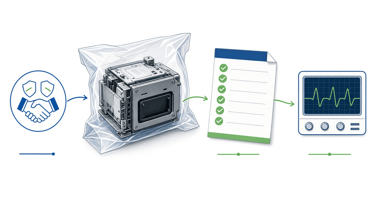
Manufacturer names and independence. This workpaper uses manufacturer names as they appear in public FDA recall and adverse-event records, and to identify compatibility and part numbers. The records provide examples of failure modes. Rongtao Medical and the authors are independent of each named manufacturer, with no affiliation, sponsorship or authorization. Pilot identifier PO-2026-TO-014, line-item pricing, serial tags and delivery timelines are illustrative.
Regulatory Scope: Who Is Bound by What
To apply regulatory references accurately during supplier onboarding, quality and procurement teams must recognize that medical device regulations impose distinct legal obligations depending on an organization's operational role. The legal force of quality system requirements, premarket standards, and postmarket inspection programs is not uniform across all market participants:
- Medical Device Manufacturers and Remanufacturers [R]. Entities that manufacture finished devices, or whose refurbishment activities alter a device's performance, safety specifications, or intended use such that they meet the definition of a remanufacturer in 21 CFR 820.3(a) (cited in earlier FDA guidance under its former designation, 21 CFR 820.3(w)), are legally bound by FDA's Quality Management System Regulation (QMSR, 21 CFR Part 820, effective February 2, 2026) 5, 6. QMSR explicitly incorporates ISO 13485:2016 by regulatory reference into 21 CFR Part 820 under 89 FR 7496 5, 6, 7. FDA inspects manufacturers and remanufacturers under Compliance Program 7382.850 (Inspection of Medical Device Manufacturers), evaluating Total Product Life Cycle (TPLC) controls across Purchasing (Clause 7.4), Traceability (Clause 7.5), and Nonconforming Product (Clause 8.3) 7, 8.
- Third-Party Servicers, Refurbishers, and Resellers. Independent service organizations, third-party parts refurbishers, and commercial resellers that perform routine maintenance and like-for-like repairs that restore original specifications are currently not subject to the requirements of the QMSR. FDA Compliance Program 7382.850 confirms this boundary in Part III, Section 4.B (pp. 43–44): "Third party refurbishers, reconditioners, servicing organizations and 'as is' resellers are currently not subject to the requirements of the QMSR [...] Self-described refurbishers, reconditioners, and servicing organizations should only be inspected as directed, or if there is reasonable evidence that the entity is remanufacturing and there is a risk to public health" 8. In our reading, routine third-party servicers and parts suppliers may obtain ISO 13485:2016 or ISO 9001:2015 certification voluntarily or to meet customer contracts or another jurisdiction’s rules. Part 820 applies to finished device manufacturers and remanufacturers. If a servicer's activities cross the legal boundary into remanufacturing, statutory manufacturer regulatory obligations attach under federal law 1, 5.
- U.S. Medicare-Participating Hospitals [R]. Equipment maintenance falls under the Conditions of Participation at 42 CFR 482.41 and 42 CFR 482.26(b)(2) 9 10. CMS memorandum S&C 14-07-Hospital states that imaging and radiologic equipment must be maintained according to manufacturer recommendations and excludes that equipment from an Alternate Equipment Management program 11.
- International Buyers and Servicers. Identify the destination market and the entity’s role. A foreign manufacturer or remanufacturer supplying a finished device for U.S. import must assess its FDA obligations, including applicable 21 CFR 807.40 requirements and exemptions. Identify whether the item is a finished device, a regulated accessory or a component supplied solely for further manufacture; those activities can have different obligations. Apply Part 807 as appropriate to an initial importer or other regulated activity. Organizations operating wholly outside U.S. jurisdiction can use FDA guidance as a voluntary benchmark alongside their domestic requirements 12.
Key to Regulatory and Engineering Norms
Throughout this workpaper, technical and compliance criteria are classified into four explicit categories:
- [R] Regulatory Requirement. Binding legal obligation enacted by statutory authorities that applies strictly to designated entities (e.g., QMSR for legally defined manufacturers and remanufacturers; CMS Conditions of Participation for Medicare-certified hospitals).
- [S] Consensus Standard. Technical criterion published by an international or national standards development organization (such as IEC, ISO, IPC, or ANSI). A standard becomes legally binding only when expressly incorporated into statutory regulation or written into commercial purchase contracts.
- [O] OEM Specification. Manufacturer-defined operating limit, tolerance, or service manual specification established for a specific equipment platform.
- [W] Workpaper Recommendation. Practical engineering protocol, model contractual clause, or default pass/fail threshold formulated by the authors to mitigate operational and clinical risks during trial orders. Buyers may adapt these recommendations to match institutional risk policies.
A combined tag means the cited rule or standard and the workpaper test serve different roles. Follow the source for its scope and use the [W] value only as the proposed buyer default.
1. Why Paper Supplier Audits Miss What a Physical Trial Order Uncovers
A refurbished part can pass dock inspection and fail weeks later in daily use. Three examples follow.
- Illustrative failure mode A (Front-end processing): A replacement front-end beamformer board throws intermittent channel dropouts and vertical image shadowing after four hours of continuous obstetric scanning, requiring clinical room shutdown.
- Illustrative failure mode B (Acoustic probe packaging): A refurbished convex abdominal probe exhibits silicone acoustic lens edge-lifting, allowing coupling gel to seep beneath the lens barrier and causing progressive acoustic signal attenuation.
- Illustrative failure mode C (Power supply aging): A high-voltage power supply module suffers thermal protection shutdown during pulsed-wave Doppler imaging because secondary filter capacitors dried out during extended warehouse storage, exhibiting elevated equivalent series resistance (ESR).
Vendor questionnaires document corporate policies, quality manuals, and warranties. Measuring how a refurbished subassembly handles transport vibration, electrical power cycling, and sustained operating temperatures requires physical inspection and empirical bench testing. The trial order protocol bridges this operational gap by shifting the vendor qualification gate from document review to verified bench performance.
1.1 The Operational Economics of a Staged Pilot Order
Compare the incremental cost of a staged trial order with the possible cost of a failed installation. Use local inputs for the purchase decision.
- Receiving verification investment [W]. Illustrative inputs for PO-2026-TO-014: 4–6 active labor hours at $75 per hour, or $300–$450. The labor includes 45 minutes for ESD handling and microscopy, 30 minutes for electrical safety screening, plus setup, phantom captures, scheduled monitoring and documentation. The 48-hour staged bench schedule is elapsed time.
- Cost of a failed installation [W]. In an illustrative outage, 6–10 appointments at $200–$400 per appointment represent $1,200–$4,000 in gross scheduled charges. Calculate unrecovered revenue or contribution using actual payer receipts and the share of appointments that cannot be rescheduled. Add incremental dispatch, freight and retest costs separately where incurred. These scenario inputs describe possible exposure. The workpaper has no measured savings.
Structuring the pilot order with a 30% commercial acceptance holdback ($1,710 across the $5,700 pilot) provides the contractual leverage needed to enforce bench clearance before releasing final payment.
1.2 Integration With Upstream Sourcing Guidance
This workpaper addresses the physical trial order phase of supplier qualification. Upstream supplier pre-screening, vendor establishment vetting, and component nomenclature have been detailed in related technical resources, including guidance on supplier establishment-registration screening under 21 CFR 807.20 12, multi-tier condition-grade classification for refurbished imaging assemblies, board part-number and revision verification, and transducer useful-life governance. The protocol described below assumes initial commercial shortlisting has occurred and focuses on the physical mechanics of verifying delivered hardware.
2. PO Specification, Legal Boundary Gate, and Pilot Design
A purchase order that says only “refurbished tested working ultrasound board” leaves hardware revision, firmware, packaging and servicing scope unspecified. Under ISO 13485:2016 Clause 7.4.2 [S], purchasing documentation must clearly state product requirements, technical specifications, and acceptance criteria prior to supplier dispatch 7.
2.1 Multi-Commodity Pilot Structure (PO-2026-TO-014)
Testing a prospective vendor using a single low-complexity cable assembly or mechanical trackball tests freight delivery speed but reveals little about technical refurbishment capability. Conversely, procuring an entire ultrasound system console imposes excessive capital expenditure for an initial screen. An effective pilot order evaluates three core commodities representing distinct engineering and failure physics within a single coordinated shipment:
- Line 1: General-Imaging Convex Transducer Probe (Qty 1, Illustrative $1,850). Curved abdominal/obstetric array probe. This commodity screens the supplier's mechanical assembly, acoustic lens bonding, piezoelectric acoustic array health, strain-relief integrity, and decontamination handling.
- Line 2: Front-End Transceiver / Beamformer PCB (Qty 1, Illustrative $2,400). High-density mixed-signal printed circuit board carrying multi-channel analog-to-digital converters, high-voltage transmit pulser switches, EEPROM identification chips, and FPGA configuration firmware. This commodity screens ESD packaging discipline, surface-mount soldering workmanship, and exact hardware/firmware revision compatibility.
- Line 3: High-Voltage Power Supply (HVPS) Module (Qty 1, Illustrative $1,450). Enclosed switching power supply providing regulated high-voltage pulser rails (typically ±50 V to ±100 V DC) and low-voltage digital logic rails (+3.3 V, +5 V, ±12 V DC). This commodity screens chassis mechanical grounding, secondary capacitor health, thermal dissipation, and electrical insulation safety under load.
Statistical Scope and Pilot Limitations [W]. A trial order of one unit per line (three units total) verifies packaging discipline, physical workmanship, revision matching, and initial electrical/acoustic performance for that specific delivery. Assess supplier consistency over Lots 2 through 4 and the continuing scorecard (Section 8.3).
| PO Line & Commodity | Illustrative PO Unit Price | Servicing Boundary Gate (FDA May 2024) | Dock & Microscopy Gate | 48-Hour Staged Bench & Safety Protocol |
|---|---|---|---|---|
| Line 1: Convex Array Probe (Qty 1) | $1,850 (Holdback $555) | Step A1/A1.1: Patient-contact materials. Applying guidance, our reading is: like-for-like strain relief and cable jacket repair is likely servicing; unvalidated lens casting or alternative adhesives is likely remanufacturing. Step A3: Ask the supplier to show that resealing restored reprocessing compatibility. | Undamaged shipping carton; signed Cleaning & Decontamination Certificate (agent on OEM list). 20x stereo microscopy: silicone lens edge seal intact, zero bubbling, strain relief bonded without tears. Labeled operating life verified. | Stage 2 staged 48-hour verification. Use the OEM or platform-approved uniformity screen. Apply PO-attached QA reference, settings and limits to baseline and exit images and uniformity. Use the approved mode sequence and load during the 38-hour load block. Apply the PO-attached cm tolerance for Hour 0 to 48 penetration. Reject a fault reproduced with the trial probe after the reference swap. Hold unattributed faults for supplier teardown and repeat applicable leakage checks. |
| Line 2: Transceiver / Beamformer PCB (Qty 1) | $2,400 (Holdback $720) | Section VII: Software/firmware boundary. Applying guidance, our reading is: reloading unmodified OEM firmware at stated version is likely servicing; modifying beamformer delay tables, MI/TI acoustic limits, or non-OEM bitstreams is likely remanufacturing. | Sealed metallized static-shielding bag (ANSI/ESD S20.20-2014); HIC card < 10% RH. IPC-A-610 Class 3 microscopy on reworked ICs: wetting fillets, side-joint length, heel fillets compliant; zero solder bridges; TIM grease intact around heatsinks. | Stage 2 Host Soak: Reconcile FAB, populated PCA, and FRU numbers. Service utility EEPROM serial and firmware version or checksum matching OEM documentation or a known-good board of the same FRU and revision [W]. 38-hour Phase B console stress script. POST/BIST zero error flags [O]. Phase C: 10 standby and 5 cold restart cycles zero faults [W]. |
| Line 3: High-Voltage Power Supply (Qty 1) | $1,450 (Holdback $435) | Step A2: Capacitor replacement. Applying guidance, our reading is: replacing capacitors with same specifications (capacitance, voltage, temp rating, footprint) is likely servicing. Step A3.1: Bypassing thermal cutouts or altering trip points is likely remanufacturing. | ShockWatch label intact (25G-50G). Optical inspection: secondary electrolytic capacitors flat-topped without venting or electrolyte leakage. AC inlet terminals and transformer silicone staking mechanically rigid. | Stage 1 Isolated Rig: IEC 62353 protective earth <= 0.3 Ω with cord, <= 0.2 Ω chassis inlet [S]; use the OEM minimum insulation resistance [O], or the proposed 2 MΩ default at 500 V DC where no OEM value exists [W]. 38-hour Phase B dynamic resistive load block: logic rails within ±2% [W], ±HV rails within OEM spec [O], AC inlet lugs <= 65 °C [W]. Line 3 Host Check: 2-hour host console integration check [W]. |
Operational receiving matrix combining servicing-boundary checks, dock inspection, and staged 48-hour bench testing across three diagnostic ultrasound commodities ($5,700 total, 30% holdback).
Source: Illustrative workpaper model (PO-2026-TO-014), Rongtao Medical editorial analysis.
2.2 Applying FDA's May 2024 Remanufacturing Boundary at Intake
On May 10, 2024, FDA issued its final guidance Remanufacturing of Medical Devices: Guidance for Industry, Entities That Perform Servicing or Remanufacturing, and Food and Drug Administration Staff 1. The guidance carries the explicit notice "Contains Nonbinding Recommendations" and establishes an analytical framework to assist industry in distinguishing servicing from remanufacturing based on the definition of a remanufacturer in 21 CFR 820.3(a) 1, 5:
- Service (p. 5). FDA describes repair or preventive or routine maintenance of a finished device after distribution to restore OEM safety and performance specifications and its original intended use 1.
- Recondition, refurbish or rebuild (p. 4). FDA describes activity that “restores a medical device to the OEM’s original specifications comparable to when new.” The device can be brought to current specifications where its performance, safety specifications and intended use do not significantly change. Examples include repair, replacement of worn parts and OEM-provided updates 1.
- Remanufacturing (p. 3). The processing, conditioning, renovating, repackaging, restoring, or any other act done to a finished device that significantly changes the finished device's performance or safety specifications, or intended use 1.
If an entity engages in remanufacturing, Section VIII of the guidance (pp. 17–21) explains that remanufacturers are generally subject to the same regulatory requirements as finished device manufacturers, including establishment registration and device listing (21 CFR Part 807), Medical Device Reporting (21 CFR Part 803), Reports of Corrections and Removals (21 CFR Part 806), Quality Management System Regulation (21 CFR Part 820), and applicable marketing authorization requirements 1, 5, 12, 13.
Use the guidance’s decision pathways to screen how each incoming part was serviced.
- Principle 1 (Change to Intended Use). FDA asks entities to assess any change to intended use (p. 6) and says a significant change is likely remanufacturing (p. 9). In our reading, enabling a clinical application or imaging mode for which the device was not configured is likely remanufacturing 1.
- Hardware Flowchart (Section VI, Figure 1) Evaluation.
- Step A1 & A1.1 (Patient-Contacting Materials). Step A1 asks whether a component, part, or material that directly or indirectly contacts body tissue is added, removed, or changed. Step A1.1 recommends conducting a risk-based assessment evaluating biocompatibility (ISO 10993) and compatibility with validated cleaning and disinfection procedures (p. 12) 1. Applying the guidance, our reading is that replacing an external cable jacket or strain-relief boot with OEM-specified materials that maintain biocompatibility and disinfectant resistance is likely servicing. Conversely, casting an unvalidated aftermarket acoustic lens or applying unverified adhesive chemistries that degrade under cleaning agents involves a significant change in materials and is likely remanufacturing 1.
- Step A2 (Component Addition, Removal, or Specification Change). Section VI.A of the guidance provides an explicit servicing example regarding electrical components: "Conversely, replacing an internal capacitor with one that has the same specifications (e.g., same capacitance, working voltage, temperature range, materials, and footprint) is not likely to significantly change device performance or safety specifications and therefore, is likely not remanufacturing" (p. 8) 1. Applying the guidance, our reading is that replacing degraded secondary electrolytic capacitors on Line 3 (HVPS) with components matching original OEM specifications (capacitance, voltage, temperature rating, and footprint) is likely servicing. Substituting an undersized capacitor or modifying output voltage rails shifts energy specifications and is likely remanufacturing 1.
- Seal-Breaking and Circuit Board Modifications (Section VI.A & Step A3). The guidance explicitly cautions in Section VI.A (p. 8) that "many activities, such as modifying the design of a printed circuit board or temporarily breaking a seal to replace a component, may result in a significant change ... and should be carefully assessed." Furthermore, Step A3 (p. 15) specifically considers whether activities that break a seal or barrier return the device to original specifications, "including its ability to be adequately reprocessed." For Line 1 (Probe), opening acoustic housing seams or replacing acoustic lenses breaks critical environmental barriers; this workpaper asks the supplier to show that resealing restored ingress protection and reprocessing compatibility [W].
- Step A3.1 (Safety Features). Step A3.1 says that removing, modifying or bypassing a safety feature, such as a fuse, alert, alarm or interlock, likely changes performance or safety specifications significantly (p. 15) 1. Applying the guidance, our reading is that bypassing a thermal cutout or altering an over-current trip point inside an HVPS module constitutes likely remanufacturing and introduces severe clinical hazards 1.
- Software and Firmware Boundaries (Section VII). FDA explicitly states in Section VII (p. 15) that the Figure 1 risk-based hardware flowchart "should not be applied to changes involving software" 1. FDA notes that "Many software changes are likely remanufacturing" (p. 15) and that activities outside its listed categories are generally considered likely remanufacturing (p. 16) 1. FDA lists 13 software activities likely outside remanufacturing. Examples include reinstalling OEM software to restore original specifications, installing an OEM-authorized update (Example S.1), executing cybersecurity scans and running diagnostic utilities 1. Applying the guidance, our reading is that reloading unmodified OEM firmware at the stated version onto an on-board EEPROM or FPGA is likely servicing. Conversely, modifying beamformer delay tables, altering Acoustic Output Display Standard (MI/TI) calculation code, or deploying non-OEM configuration bitstreams is likely remanufacturing 1.
- Appendix A Cautionary Note. Appendix A provides illustrative examples, but explicitly warns: "Note that these generalized examples do not necessarily account for every possible detail, risk, or consideration that an entity should evaluate, and should not be taken to mean that the changes described are or are not definitively remanufacturing" (p. 23) 1. Technical determinations depend on device-specific risk evaluations.
- Servicing Decision Record. FDA's guidance asks for the product name and applicable model and serial numbers, dates of work and determination, a device description, a description of activities and affected parts or materials, the remanufacturing determination, supporting document references and signatures. Appendix B illustrates one possible approach (p. 10 and Appendix B) 1. This workpaper recommends keeping the supplier's signed attestation with the purchasing records [W]. It records the supplier's representation. Verify it with the applicable service record and bench evidence.
2.3 Model Purchase Order Contract Clauses
Notice: The following contract clauses represent illustrative model language formulated by the authors as drafting aids for healthcare technology management teams and ISOs [W]. Organizations should adapt these terms with legal and procurement counsel.
Buyers embed four proposed clauses directly onto the face of PO-2026-TO-014 or incorporate them into an attached Quality Agreement Addendum:
- Clause A (Exact Configuration and Revision Lock) [W]. "Seller shall deliver the exact OEM base part numbers, hardware engineering dash revisions, and unmodified OEM firmware at the stated versions specified on each purchase order line. No dash-revision substitutions, unlisted board-level engineering change orders (ECO), or cross-generational firmware builds shall be accepted without Buyer's prior written Engineering Change Approval."
- Clause B (Servicing Boundary Representation) [W]. "Seller represents and warrants that all refurbishment, component replacement, calibration, and testing performed on delivered items constitute servicing, and not remanufacturing, as FDA's May 10, 2024 guidance describes those terms, restoring the subassemblies to original OEM safety, electrical, thermal, and acoustic performance specifications without significant change to intended use, safety margins, or performance specifications. For assemblies where housing seals were opened (such as acoustic probe resealing), Seller warrants that fluid ingress protection and disinfectant compatibility have been fully verified. Seller shall provide component traceability records upon reasonable audit request."
- Clause C (Protective Packaging and Pre-Shipment Evidence) [W]. "Electrostatic-sensitive assemblies shall be packaged in heat-sealed metallized static-shielding bags conforming to ANSI/ESD S20.20, enclosing active desiccant and a fresh humidity indicator card reading below 10% relative humidity upon packaging. Transducer probe assemblies shall include a signed Cleaning and Decontamination Certificate documenting probe serial number, cleaning date, chemical agent used, and an attestation that the agent appears on the OEM's validated compatibility list. Seller shall provide serial-linked bench test documentation or test confirmation matching delivered serial tags."
- Clause D (30% Acceptance Holdback and SCAR Warranty) [W]. "Thirty percent (30%) of the total line-item invoice value ($1,710 across PO-2026-TO-014) shall be withheld pending Buyer's documented completion of dock inspection, IPC-A-610 Class 3 microscopy at the revision named on the PO, IEC 62353 electrical safety screening, and successful completion of the staged 48-hour verification, including the 38-hour Phase B block, and the applicable two-hour Line 3 host check against the pre-dispatch purchase order or quality-addendum attachment within ten (10) business days of delivery. Any nonconformance shall trigger immediate quarantine, an RMA return at Seller's freight expense, a written SCAR response within five (5) business days, and full credit or exact revision-matched replacement. Where Buyer verifies by supervised clinical installation, the period is thirty (30) days from installation."
Before dispatch, attach the bench acceptance matrix, Line 1 QA reference, settings and limits, and the Section 5.4 penetration tolerance to the purchase order or quality addendum. Judge holdback release against that attachment [W]. If an unresolved acceptance criterion or observation places a unit on hold, notify the seller in writing, quarantine the unit, keep the holdback withheld and suspend the acceptance period until the hold closes [W]. For suppliers requiring full prepayment, agree the same attachment and hold procedure in writing as the condition for refund or exact replacement at the seller’s freight cost. Keep the first order to the pilot quantity [W].
3. Receiving Dock Controls: Packaging, ESD Protection, and Stereo Microscopy
Incoming verification begins the moment courier cartons arrive at the receiving dock. Fragile piezoelectric elements, heavy transformer inductors, and static-sensitive CMOS preamplifiers are vulnerable to rough freight handling, ungrounded unboxing, and environmental extremes.
3.1 Freight Integrity, Mechanical Indicators, and Biohazard Isolation
Receiving personnel inspect outer shipping containers before opening seals or cutting packaging tape:
- Airway Bill and Physical Carton Audit [W]. Verify that carrier waybills (DHL, FedEx, UPS, or specialized medical freight) and commercial invoices match the purchase order and packing slip. Photograph all six faces of the outer corrugated cartons, documenting crushed corners, fork punctures, water staining, or tampered tape seals.
- Shock and Tilt Mechanical Indicators [W]. Inspect mechanical drop and tilt indicators (e.g., ShockWatch and TiltWatch labels, rated at 25G to 50G impact [W]) mounted on heavy assemblies such as Line 3 (HVPS) and high-value probe flight cases. High-mass ferrite switching transformers and filter inductors can fracture solder fillets or lift printed circuit pads under severe transit shocks. An activated indicator triggers heightened internal optical teardown inspection before applying electrical power; this workpaper's default is rejection if internal mechanical damage is detected [W].
- Transducer Biohazard and Decontamination [W]. Check that Line 1 arrives in an intact clean barrier with a signed record giving the serial number, cleaning date and agent. MHRA Medical Device Alert MDA/2012/037 (GOV.UK summary reference MDA/2012/038) reported a death that may have been associated with a transoesophageal probe that was not decontaminated between patients 14. This workpaper applies the caution to probes arriving from a supplier [W].
3.2 Electrostatic Discharge Controls for Line 2 (ANSI/ESD S20.20)
Diagnostic ultrasound front-end transceiver boards integrate highly sensitive multi-channel low-noise preamplifiers, high-voltage analog switches, and high-speed analog-to-digital converters fabricated with sub-micron gate oxides. Electrostatic discharges well below human tactile perception (<100 V, compared to the ~3,000 V felt spark) can breach gate oxide dielectrics. Latent ESD damage often causes progressive gate oxide breakdown rather than immediate catastrophic failure, allowing an improperly handled board to pass brief functional checks only to fail intermittently after weeks in clinical operation.
FDA formally recognizes ANSI/ESD S20.20-2014 (Protection of Electrical and Electronic Parts, Assemblies and Equipment, Recognition Number 5-98) as a consensus standard 15. Commercial purchase orders may specify ANSI/ESD S20.20-2021 by contract [W]. Receiving technicians unpack and inspect Line 2 exclusively within an ESD-protected area (EPA) meeting standard controls:
- Personnel Grounding [S/W]. Technicians wear calibrated wrist straps tested daily. Under ANSI/ESD S20.20-2014 Table 2, the total wrist strap system resistance must be less than 3.5 × 10^7 Ω (35 MΩ) [S]. This workpaper adds a lower limit of 0.75 MΩ [W].
- Dissipative Work Surfaces [S/W]. Benchtop dissipative mats are grounded. Under ANSI/ESD S20.20-2014 Table 3, worksurface resistance to ground must be less than 1.0 × 10^9 Ω [S]. This workpaper keeps worksurface resistance between 1.0 × 10^6 Ω and 1.0 × 10^9 Ω [W].
- Static-Shielding Packaging Verification [W]. Technicians confirm that Line 2 is enclosed in an undamaged, heat-sealed metallized static-shielding bag (Faraday cage design). Non-shielding pink anti-static poly bags (which merely reduce charge generation without shielding external electrostatic fields) or bare bubble wrap represent an immediate dock nonconformance.
- Moisture Handling and Indicator Cards [W]. IPC/JEDEC J-STD-033 governs moisture-sensitive bare surface-mount devices prior to high-temperature reflow soldering, where trapped moisture causes package delamination ("popcorning") at temperatures exceeding 220 °C. While popcorning does not occur during ambient operation or 30–35 °C bench soak, the presence of an active desiccant pouch and a fresh Humidity Indicator Card (HIC) provides valuable buyer assurance of packaging hermeticity during transit. Technicians read the HIC immediately upon opening against the card's printed color key. If the card shows more than 10% RH, the assembly is flagged for moisture exposure, and any subsequent board-level component rework requires controlled low-temperature bakeout in accordance with manufacturer instructions.
3.3 Stereo Microscopy Workmanship Inspection (IPC-A-610 Class 3)
Following ESD unbagging, a quality engineer performs unpowered optical inspection under 10x to 40x stereo microscopy. Workmanship criteria are benchmarked in this example against IPC-A-610H Class 3. Record the agreed revision on the PO. Class 3 applies to High Performance / Harsh Environment Electronic Assemblies, covering equipment where continued high performance or performance-on-demand is critical [S] 16. These Class 3 criteria are applied specifically to supplier-reworked, soldered, or replaced components on refurbished subassemblies [W]; untouched factory-original joints are evaluated for baseline structural integrity:
- Reworked IC Leads and Solder Fillets [S/W]. Replaced surface-mount integrated circuits (pulsers, transceivers, multiplexers) are inspected for wetting fillets, side-joint length, and heel fillet height meeting IPC-A-610 Class 3 principles 16. Solder bridging, cold or disturbed crystalline joints, lifted circuit traces, or substrate blistering trigger nonconformance [W].
- Passive Component Placement and Rework [S/W]. Replaced chip capacitors and resistors must be properly centered across landing pads with solder rise meeting Class 3 wetting limits 16. Tombstoned components, termination overhang exceeding 25% of component width, or uninsulated engineering change jumper wires traversing high-voltage pulser traces trigger rejection [W].
- Cleanliness and Conformal Coating [W]. Reworked regions must be thoroughly cleaned of flux residues. Sticky rosin residues or dendritic ionic crystals (indicating incomplete post-soldering wash) trigger nonconformance due to high-voltage leakage risks. Where conformal coating is present, inspection under ultraviolet illumination must verify uniform coverage without voids or bubbling.
- Mechanical and Acoustic Physical Checks (Line 1 & Line 3) [W].
- Line 1 (Probe). Inspect the acoustic silicone lens under magnification for pinholes, edge-lifting along the housing boundary, localized gouges, or swelling from incompatible cleaning solvents. The strain-relief boot must be securely bonded to the housing collar without tears exposing internal coaxial shielding. Physical housing seam separation risks are illustrated by recall Z-2517-2023, and casing fluid leakage risks are illustrated by recall Z-1490-2026 (detailed in Section 6.1) 3.
- Line 3 (HVPS). Inspect secondary bulk electrolytic capacitors for swollen tops, ruptured pressure vents, or electrolyte seepage stains. Check AC mains input terminals, fuse holders, and transformer brackets for mechanical rigidity and silicone staking integrity.
4. Multi-Layer Identity Lock, Hardware/Firmware Parity, and Useful-Life Governance
A subassembly with compliant solder joints and pristine packaging can still disrupt clinical operations if it carries an incompatible hardware dash revision, a mismatched firmware hash, or remarked commercial silicon, or if an acoustic transducer has exceeded its labeled operating life.
4.1 Multi-Layer Hardware and Firmware Reconciliation on Line 2
Ultrasound front-end electronics use layered part-numbering schemes. A transceiver board can carry three part numbers.
- Bare Fabrication Number (FAB P/N). Silkscreened or etched directly onto the raw copper-clad laminate (e.g.,
REV 03 FAB), representing the unpopulated bare circuit board. - Populated Assembly Number (PCA P/N). Printed on an adhesive barcode label affixed after component soldering, specifying the exact component stuffing option, active silicon variants, and factory configuration.
- Field Replaceable Unit Number (FRU P/N). The commercial service catalog number specified in OEM technical manuals and purchase orders, which may bundle specific firmware kits, bracket revisions, or mounting hardware.
Receiving personnel must reconcile all three numbers against the purchase order specification [W]. Across major diagnostic ultrasound architectures, successive hardware dash revisions (e.g., Rev A versus Rev C) can introduce functional modifications: reassigned backplane power pins, altered differential clock terminations, or updated FPGA memory layouts. Installing an incompatible dash revision simply because backplane edge connectors mate physically can cause bus contention, localized power regulator overheating, or timing artifacts during multi-beam processing. Hardware port-switching risks associated with component change controls are illustrated by recall Z-1757-2024 (Section 6.1) 3.
During initial console connection (Section 5), technicians capture three digital identity parameters directly into the receiving record [W]:
- Host service utility query of the board's embedded EEPROM serial number and hardware configuration string.
- Firmware version or checksum from the service utility, compared with OEM service documentation or a known-good board of the same FRU and revision, plus a hash where the utility reports one.
- Built-In Self-Test (BIST) initialization log confirming that all transmit/receive channel addresses enumerate without reporting hardware conflict flags.
4.2 Counterfeit and Salvage Screening on Reworked Assemblies
Refurbished electronic subassemblies sourced through secondary distribution channels carry risks of remarked components or salvaged integrated circuits. During stereo microscopy, quality engineers execute targeted counterfeit screening focused on supplier-reworked components [W]:
- Marking Permanence and Surface Texture [W]. Inspect component body surfaces under oblique lighting. Authentic factory packages display uniform molded epoxy textures with clear markings. Uneven surface finishes, chemical sanding scratches, or "blacktopping" (a thin layer of epoxy paint applied to conceal original part numbers prior to re-marking) indicate remarked parts. Gently swab replaced components with laboratory-grade isopropyl alcohol using a cotton swab; ink smearing or paint lifting is a reason to quarantine the unit and request component provenance and traceability from the supplier [W].
- Date Code and Lot Consistency [W]. Examine multi-channel IC arrays (such as octal transmit pulser ICs or matched low-noise preamplifier banks). Replaced components across a single functional bank should carry consistent manufacturer logos, pin-one orientation dimples, and plausible date-code formats matching legitimate production vintages.
- Component Lead Finish and Coplanarity [W]. Replaced surface-mount packages must display uniform lead coplanarity and smooth solder finishes. Scraped lead frames, ragged edges, or excessive solder buildup on component leads indicate salvaged parts de-soldered from discarded donor circuit boards.
- Thermal Interface Material (TIM) Integrity [W]. Verify that thermal interface pads or cured thermal grease visible around FPGA heatsink margins on Line 2 and power MOSFET heatsink brackets on Line 3 are fresh, resilient, and correctly positioned, without performing destructive teardown that voids supplier warranty [W].
4.3 Useful-Life Governance vs. End of Commercial Support (Line 1 Probe)
A critical distinction in healthcare technology management separates the end of commercial OEM support from a device's validated labeled useful life:
- End of Commercial Support / End of Life (EOL). A commercial milestone where an OEM discontinues manufacturing new replacement parts or offering direct service contracts for a legacy system. An imaging probe operating past an OEM commercial service milestone can continue in safe clinical service provided it operates within its original technical specifications and maintains physical and electrical integrity.
- Validated Labeled Useful Life. A defined performance and safety envelope established by the manufacturer and validated in device labeling or Instructions for Use (IFU). Transducer piezoelectric arrays, acoustic backing blocks, and lens bonding adhesives experience cumulative acoustic energy absorption, cleaning chemical exposure, and thermal cycling. Beyond labeled useful life, the manufacturer has not validated performance, and fatigue or attenuation may have progressed.
FDA recall records illustrate the importance of useful-life limits in probe maintenance. In Class II recall Z-2064-2025 (Philips Ultrasound, Inc., X5-1 matrix array transducer), the recorded recall reason states: "Ultrasound transducer devices were refurbished beyond their useful life" 3. Similarly, Class III labeling actions Z-1622-2026 (Philips Mini Multi TEE probe) and Z-2367-2025 (D2TCD Doppler transducer) were initiated by the firm to provide labeling clarifications explicitly defining useful-life limits 3.
Where to find useful-life data: Technicians locate labeled operating life in the OEM's Instructions for Use (IFU), technical service manuals, or device labeling. Electrical safety screening and phantom tests check current performance. In our reading, the manufacturer’s labeled useful-life limit remains the basis for the decision [W]. Apply the following receiving policy.
- If a refurbished transducer probe remains within its OEM-labeled useful life, log the serial number, manufacturing date, and refurbishment history in the receiving traveler.
- Reject a probe at or beyond its labeled useful-life limit under this workpaper [W]. For a probe whose labeling and service documentation state no useful-life limit and whose operating history is unknown, the default is also rejection. An exception for the unknown-history case requires documentation establishing that continued use is permissible and sign-off by clinical engineering and risk management. That assessment adds a control. It neither extends manufacturer validation nor overrides applicable law or mandatory maintenance and replacement instructions. Follow the manufacturer’s maintenance instructions and applicable requirements, including CMS S&C 14-07-Hospital for covered U.S. imaging equipment 11.
5. Electrical Safety and the 48-Hour Staged Bench Verification Protocol
Visual inspection and part-number verification screen mechanical damage and configuration mismatches. Calibrated electrical safety testing and an extended thermal soak can detect dielectric insulation breakdown, high-voltage pulser rail droop and intermittent channel dropouts.
5.1 Premarket Recognition Realities vs. Post-Repair Operational Standards
Clinical engineering buyers must understand the structural relationship between standards recognized for premarket device submissions and those governing post-repair bench testing:
- Premarket Standards for Finished Device Clearance. FDA's Recognized Consensus Standards database lists IEC 60601-2-37:2024 Edition 3.0 under Recognition Number 12-380 (effective May 26, 2025, with no transition expiry listed) 17. This runs concurrently with IEC 60601-2-37:2015 Edition 2.1 under Recognition Number 12-293, for which FDA accepts declarations of conformity in premarket submissions until July 2, 2028 18. That date governs premarket submissions only. Post-repair testing follows the OEM service procedure and the facility’s requirements.
- Post-Repair Bench Testing Standards. Four standards that are central to routine aftermarket refurbishment and biomedical testing return zero hits in FDA's premarket recognized consensus database search 19: IEC 62353:2014 (medical electrical equipment recurrent test and test after repair) 2, IEC 63077:2019 (refurbishment practices for medical imaging equipment) 20, IPC-A-610 (electronic assembly acceptability) 16, and ISO 13485:2016 itself 7. These standards address postmarket testing, refurbishment and quality management. While ISO 13485 carries regulatory force for manufacturers through direct incorporation into 21 CFR Part 820 5, 6, the workpaper recommends naming the applicable post-repair and assembly standards in the purchase order [W].
| Standard / Regulation / Framework | Regulatory Status & Bound Entities | Key Clause or Terminology | Workpaper-Recommended Evidence |
|---|---|---|---|
| 21 CFR Part 820 (QMSR) / FDA Compliance Program 7382.850 | Statutory requirement [R] for manufacturers and remanufacturers under 21 CFR 820.3(a). CP 7382.850 states third-party servicers and resellers are currently not subject to QMSR. | QMSR incorporates ISO 13485:2016 by reference: Cl. 7.4 (Purchasing), Cl. 7.5 (Traceability), Cl. 8.3 (Nonconforming Product). Remanufacturers bound by full controls. | Signed Remanufacturing Servicing Attestation referencing FDA May 2024 guidance principles. Validated vendor ISO 13485 certificate. Supplier FDA registration where required. |
| ANSI/ESD S20.20-2014 / ANSI/ESD S20.20-2021 | ANSI/ESD S20.20-2014 recognized by FDA under Recognition Number 5-98 [S]. Applies to third-party suppliers when written into commercial purchase contracts [W]. | Table 2 (Wrist strap system < 3.5 × 10^7 Ω) [S]. Table 3 (Worksurface < 1.0 × 10^9 Ω) [S]. Dissipative packaging and Faraday cage static-shielding bags. | Personnel wrist strap daily logs (0.75-35 MΩ) [W]. Bench mat grounding verification. Metallized shielding bag inspection; fresh HIC card (<10% RH); desiccant pouch verification. |
| IPC-A-610H / IPC-A-610J | Consensus standard published by IPC [S]. Returns zero hits in FDA premarket database. Applied by commercial contract to evaluate electronic assembly acceptability [W]. | Class 3 (High Performance / Harsh Environment Electronic Assemblies). SMT wetting fillets, heel fillets, lead coplanarity, and flux cleanliness. | Optical stereo microscopy log (10x-40x) on supplier-reworked ICs and passive components. Counterfeit marking permanence alcohol-swab verification. |
| IEC 60601-2-37 (Ed 2.1 & Ed 3.0) | Premarket consensus standard for diagnostic ultrasound [S]. Ed 3.0 (Rec 12-380) recognized; Ed 2.1 (Rec 12-293) declarations accepted in submissions until July 2, 2028. | Particular requirements for basic safety and essential performance of ultrasonic medical diagnostic equipment. Clause 201.11 type-test conditions. | The premarket transition covers declarations in premarket submissions. Use the applicable OEM or approved platform-specific temperature criterion for post-repair verification. |
| IEC 62353:2014 | International standard for recurrent testing and test after repair [S]. No match in FDA’s recognition database search. Recommended by this workpaper [W]. | Clause 5.3.2.2 Protective earth resistance. Clause 5.3.3 Insulation resistance. Clause 5.3.4 Applied-part leakage current. | Protective earth bond <= 0.3 Ω with cord, <= 0.2 Ω at inlet [S] (adopted as subassembly benchmark [W]). Use the manufacturer’s insulation resistance minimum [O] or the 2 MΩ default where none is specified [W]. Calibrated analyzer printout attached to NCR. |
| IMDRF / FDA MDR Adverse Event Codes | International terminology used in FDA’s MDR code tables. Recommended here for NCR coding [W]. | Annex A (Medical Device Problem): A090204 (Image Display Error/Artifact), A090208 (Poor Quality Image), A070802 (Intermittent Loss of Power). Annex G (Component): G02005 (Circuit Board), G0201206 (Transducer), G04034 (Connector/Coupler). | Digital NCR recording purchase order line, serial number, failure timestamp, and IMDRF code pairs. Objective telemetry (thermal IR stills, scope waveforms) attached. |
Comparative map distinguishing legally binding requirements, consensus technical standards, and workpaper-recommended evidence for refurbished ultrasound subassembly qualification.
Source: Rongtao Medical cross-reference of the FDA, ANSI/ESD, IPC, IEC and IMDRF documents cited in this article.
5.2 Staged Electrical Safety Screening Protocol
IEC 62353:2014 is the IEC standard for recurrent tests and tests after repair 2. This workpaper recommends its methods [W].
To prevent unregulated power rails from damaging the trial beamformer board or host test console, electrical verification follows a strict staged progression:
#### Stage 1: Line 3 (HVPS Module) Standalone Screening [W] Before connecting Line 3 to any active console or test backplane, mount the power supply on an isolated test fixture or sacrificial test chassis powered through an isolation transformer:
- Protective Earth Continuity [S/W]. Measure resistance from the protective earth ground pin of the mains inlet to all exposed conductive chassis surfaces using an electrical safety analyzer. Under IEC 62353:2014 Clause 5.3.2.2, protective earth resistance must not exceed 0.3 Ω when measured with the power supply cord in circuit (detachable or non-detachable), or 0.2 Ω when measured at the appliance inlet or bare chassis ground point without the power cord [S] 2. These limits are established in IEC 62353 for finished medical electrical equipment; this workpaper adopts them as an engineering benchmark for an isolated power supply subassembly on a test fixture [W].
- Insulation Resistance [S/O/W]. IEC 62353:2014 lists 2 MΩ or more as a commonly accepted value for Class I mains part to protective earth at 500 V DC. The manufacturer's specified minimum takes precedence [O]. This workpaper uses 2 MΩ where no OEM value exists [W] 2.
- Isolated Rail Regulation and Ripple [W/O]. Energize Line 3 on the bench into a multi-channel resistive dummy load matching nominal cart impedance. Verify that low-voltage logic rails (+3.3 V, +5 V, ±12 V) remain within ±2% of nominal voltage [W] and that high-voltage pulser rails (±50 V to ±100 V DC) remain within OEM service tolerances [O]. Measure switching ripple on an oscilloscope; apply the OEM ripple limits [O]. Where the OEM gives none, this workpaper uses <50 mVpp on logic rails and <150 mVpp on HV pulser rails [W].
Power-inlet connection overheating risks are illustrated by recall Z-0136-2025 (Section 6.1) 3.
#### Applied-Part Leakage Screening: Line 1 (Transducer Probe) [S/W] A qualified biomedical technician selects the test configuration and leakage limits for the exact probe, host console, and applied-part classification (Type BF or Type CF) using the manufacturer's service documentation and IEC 62353:2014 Clause 5.3.4 [S] 2. Record the measurement method, calibrated safety analyzer model, serial numbers, and measured values. Use a conductive liquid fixture only if the OEM service procedure explicitly authorizes it and defines the bath immersion limits and electrolyte medium. Hold the probe for technical clarification until the approved procedure and specific leakage limits are confirmed [W].
5.3 The 48-Hour Staged Bench Verification Protocol
Brief functional tests can miss thermal drift in power MOSFETs, rising capacitor ESR, thermal micro-cracking in solder joints and lens delamination. Use the 48-hour staged program below to look for those faults under controlled load and record the limits of the fixture [W].
Protocol Limits and Trade-Offs [W]. A pass leaves residual risk from latent ESD damage, cumulative disinfectant exposure and long-term fatigue. Observe the manufacturer’s limits on run duration, duty cycle and thermal load throughout the bench sequence.
#### Staging Definitions and Execution Architecture [W] The protocol uses three stages and a final Line 3 host integration step.
- Stage 0: Receiving Dock, ESD Verification, and Stereo Microscopy (Lines 1, 2, 3 completed within Day 1–2).
- Stage 1: Standalone HVPS Electrical Safety and Dynamic Resistive Load Testing (Line 3 mounted on isolated test rig; 48-hour staged schedule with a 38-hour Phase B load block on the dedicated bench).
- Stage 2: Host Service Console Soak and Multi-Commodity Integration (Lines 1 and 2 installed in dedicated engineering test console powered by an in-house golden power supply during their staged 48-hour schedule, including the 38-hour Phase B load block).
- Line 3 Host Integration [W]. Stages 1 and 2 can run concurrently. After both pass, fit Line 3 to the host with the known-good Line 2 reference board installed. Run the two-hour integration check on power sequencing, soft-start inrush and console self-test before release. Allow about 50 hours of bench time when Stages 1 and 2 run in parallel.
#### Bench Safety Precautions [W] Testing energized high-voltage switching supplies and high-power acoustic transducers requires strict bench safety controls [W]:
- Use the approved energized test setup and automatic shutdowns specified in the facility procedure. For this illustrative rig, the shutdown sensor reads the designated power-stage monitoring point. The separate receiving rejection threshold applies to the AC inlet lug. Record both locations and trip settings in the test plan [W].
- For Line 1 (Probe), observe OEM duty-cycle limits and manufacturer liquid immersion depth limits. Doppler segments in the approved mode sequence must run into an acoustic load bath, a tissue-mimicking phantom or an acoustic absorber consistent with the approved bench procedure [W].
- Lens surface temperature during acoustic soak is measured using a calibrated surface thermocouple placed at the phantom-lens interface, or by momentarily uncoupling the probe to capture an immediate long-wave infrared (IR) thermal camera reading [W].
#### 48-Hour Sequential Bench Execution Matrix
| Bench Phase | Time Window | Line 1: Convex Probe (Stage 2 Host) | Line 2: Beamformer PCB (Stage 2 Host) | Line 3: HVPS Module (Stage 1 Rig) | Quantitative Pass/Fail Threshold & Basis |
|---|---|---|---|---|---|
| Phase A: Cold Boot & Baseline | Hours 0–4 | Screen applied-part leakage before acoustic operation as described in Section 5.2. Read the probe EEPROM ID and run the applicable OEM or platform-approved uniformity screen [W]. Capture a baseline tissue-mimicking phantom image and record the maximum depth of penetration in cm, dead zone, caliper accuracy and axial/lateral resolution [W]. Record the applicable OEM or approved platform-specific QA reference, image settings, baseline and exit limits, and the phantom position in the traveler. Use the criteria attached to the PO or quality addendum before dispatch [W]. | Execute console POST and Built-In Self-Test (BIST); export EEPROM serial and FPGA firmware version or available checksum; calibrate TGC and channel gain linearity; record baseline 200-frame cineloop. | Measure cold startup rail rise times on isolated load; verify idle voltage tolerances (±2% on logic rails [W], OEM spec on ±HV rails [O]); record switching ripple (mVpp); verify cooling fan tachometer signal. | Zero BIST error flags [O]; baseline images meet the documented OEM or approved platform-specific QA limits [O/W]; baseline thermal IR profile logged [W]. |
| Phase B: Thermal Load Soak | Hours 4–42 | Run the approved Color Doppler, pulsed-wave and B-mode sequence in the compatible acoustic load for Hours 4–42; log lens surface temperature at Hours 4, 18, 30, and 42 via thermocouple or immediate IR read [W]. | Run continuous automated multi-channel stress script inside closed service cart chassis (ambient cart internal temp 30–35 °C [W]), driving maximum beamformer channel count and memory DMA bandwidth. | Dynamically cycle pulser load bank between idle and peak continuous-wave/Doppler demand; monitor thermal rise on AC inlet lugs, transformer core, and secondary bulk capacitors. | Transducer surface temperature stays within the limit in the applicable OEM service procedure or approved platform-specific QA plan [O/W]; HVPS AC inlet lugs <= 65 °C [W]; zero channel dropouts [O]. |
| Phase C: Hot Power Cycling & Exit QA | Hours 42–48 | Inspect silicone lens under 20x magnification for blistering, edge lifting, or gel weeping; repeat the phantom scan and the approved uniformity check. Verify exit images against the same applicable QA limits. Re-verify warm IEC 62353 applied-part leakage 2. | Perform 10 rapid warm standby/wake cycles and 5 complete AC cold-restart cycles (30-second unpowered pause [W]) under continuous video logging; verify zero boot freezes or display artifacts. | Monitor soft-start inrush current and rail sequencing across all 10 standby cycles and 5 cold restarts [W]; repeat warm IEC 62353 protective earth resistance measurement 2. | Absolute change in maximum depth of penetration between Hours 0 and 48 within the predefined platform-specific tolerance in cm under Section 5.4 [W]; exit images and uniformity meet the documented QA limits, with an unattributed abnormality following the Section 7.2 quarantine and supplier teardown disposition [O/W]; warm earth bond <= 0.3 Ω with cord, <= 0.2 Ω at inlet [S] 2; zero intermittent power resets [O]. |
Threshold Key: [S] Consensus Standard; [O] OEM Specification; [W] Workpaper Recommendation.
The 48-hour bench schedule has four hours for baseline, 38 hours for the Phase B load block and six hours for exit checks. Run the two-hour Line 3 host integration after Phase C. Before testing, document the permitted mode sequence, ambient and phantom conditions, temperature ceiling and shutdown settings from the OEM service procedure or approved platform-specific QA plan. Hold testing when an applicable safe limit or operating condition is unresolved [W].
5.4 Test Environment Calibration and Marginal Defect Criteria
Use the following controls to distinguish a fixture artifact from a part fault:
- Lead Zeroing in Earth Bond Testing [S/W]. Under IEC 62353, technicians must zero-balance safety analyzer test leads before recording chassis earth resistance on Line 3 2. Uncompensated test lead resistance (typically 0.08 Ω to 0.12 Ω) can falsely push a compliant 0.15 Ω ground bond past the 0.20 Ω chassis threshold [W].
- Phantom thermal conditioning and penetration measurement [W]. Condition the tissue-mimicking phantom according to its instructions and record its temperature and position. At Hours 0 and 48 capture the same plane at the same preset, depth, output, gain and TGC. Use the console calipers to measure in cm the maximum depth of discernible speckle under the facility’s defined image criterion. Repeat captures under the approved QA plan and calculate the absolute difference between the median depths. Predetermine the permissible difference and repeatability allowance from the approved platform-specific criterion. Apply this change limit as a stability check in addition to both baseline and exit image acceptance. If the image criteria, measurement or tolerance are unresolved, or repeatability is unacceptable, hold for the applicable OEM or qualified QA procedure.
- Transducer uniformity screen [W]. Use the applicable OEM or platform-approved screen to look for repeatable nonuniformity, dropouts or visible artifacts under controlled settings. Record the method, reference and pass criteria. Hold a probe with an unresolved abnormality and use an applicable OEM diagnostic or compatible validated electronic test if element-level localization is needed. Release requires documented acceptable baseline and exit images. A screening image alone supports a uniformity judgment and gives no element count. If the reference swap in Section 7.2 leaves the fault unattributed, use the fourth disposition row: quarantine, provisional component code G07003 and supplier teardown [W].
5.5 Alternative Verification Pathways for Facilities Without Dedicated Consoles
Use one of the following paths if the department lacks a matching engineering console, service software keys or a tissue-mimicking phantom [W]. They are ordered by how closely they reproduce the internal Stage 2 soak.
- Pathway 1: Third-Party Accredited Laboratory Verification (Highest Alternative Assurance) [W]. Contract an independent biomedical engineering service or testing laboratory to execute dock microscopy, IEC 62353 safety screening, and console load soak prior to final facility delivery. Provides independent technical evidence while protecting facility consoles from unverified hardware.
- Pathway 2: Supplier-Witnessed Video Testing (Intermediate Assurance) [W]. Require the vendor to provide continuous, timestamped video documentation of the subassembly undergoing burn-in on a compatible console at their technical facility, showing serial-matched labels, oscilloscope rail ripple traces, and phantom baseline captures. Buyers must recognize that video represents supplier-generated evidence rather than an independent check; receiving personnel must still verify physical identity, ESD packaging, stereo microscopy, and Stage 1 electrical safety screening upon delivery [W].
- Pathway 3: Supervised Scheduled Clinical PM Integration (Lowest Assurance / Highest Residual Risk) [W]. If the subassembly must be evaluated directly on the facility's clinical console, schedule the installation during planned evening or weekend preventative maintenance. Residual Risk Notice. Installing an unverified refurbished component directly into a clinical system risks console backplane damage and unexpected downtime during subsequent scanning. To mitigate this risk:
- Exclusion. High-voltage power supplies (Line 3) are strictly excluded from direct clinical installation unless a standalone resistive load test and electrical safety screen have been performed on an isolated bench [W].
- Part Retention. Retain the removed known-good part on-site for immediate re-installation if unexpected errors occur [W].
- Clinical Release Gates. Complete the OEM post-repair procedure, including its diagnostic tests, and perform facility electrical safety testing on the entire system 9 11. Complete the documented equipment QA required by the facility. For routine equipment QA, the facility may use the guide identified by AIUM’s accreditation standards (Version 2.0) 21. For this workpaper pathway, before the first patient is scanned, capture the Phase A phantom images and run the uniformity screen on the clinical console. Judge both against the documented QA limits. Run the approved mode sequence for four supervised hours within OEM duty-cycle limits and repeat the captures under Section 5.4 [W].
- Holdback Alignment. Maintain the 30% invoice holdback across an extended 30-day clinical observation period [W].
6. Choosing Bench Checks From Recalls and Adverse-Event Reports
Recall and MDR databases give engineering context for a trial order. The counts describe reports and recall records. Assess suppliers and defect rates with delivery and exposure data.
6.1 FDA Recall Analysis Across Diagnostic Ultrasound (527 Records / 267 Events)
An audit of FDA's medical device recall and enforcement datasets across diagnostic ultrasound product codes IYN (Ultrasonic Pulsed Doppler Imaging System, 21 CFR 892.1550), ITX (Diagnostic Ultrasonic Transducer, 21 CFR 892.1570), and IYO (Ultrasonic Pulsed Echo Imaging System, 21 CFR 892.1560)—excluding 23 intravascular catheter records categorized under product code OBJ—identifies 527 product recall records representing 267 deduplicated recall events spanning April 11, 2000 through March 2, 2026 (with 298 records in IYN, 147 in ITX, and 82 in IYO) 3, 22.
View chart data
| Category | IYN (Pulsed Doppler Systems) | ITX (Diagnostic Transducers) | IYO (Pulsed Echo Imaging Systems) |
|---|---|---|---|
| Device Design | 112 | 23 | 15 |
| Software design | 94 | 5 | 25 |
| Process control | 8 | 49 | 4 |
| Other (FDA label) | 24 | 30 | 4 |
| No Marketing Application | 2 | 18 | 1 |
| Component design/selection | 11 | 0 | 6 |
| Other 20 FDA Labels | 47 | 22 | 27 |
The 527 recall records cover 267 events. One firm’s useful-life labeling clarification contributes 80 records, initiated in two batches in July and September 2025. Multi-record actions affect the counts.
- Reflects official FDA root_cause_description fields across 527 recall records (298 IYN, 147 ITX, 82 IYO) representing 267 deduplicated recall events, excluding 23 OBJ catheter records. 'Other 20 FDA Labels' (96 records) includes Software change control (15), Nonconforming Material/Component (13), Process design (13), Under Investigation by firm (11), Software Design Change (7), Software Manufacturing/Software Deployment (5), Software design (manufacturing process) (4), and Release of Material/Component prior to receiving test results (4). Combined, the five official FDA software-related root causes total 155 records across the three codes. Classification data matched for 399 records: 299 Class II (150 events), 83 Class III (4 events), and 17 Class I (11 events; all 17 Class I records involved contaminated ultrasound gel and lotion consumables under ITX). None of the 399 classified records for a console, probe, board, or power supply is Class I. 128 legacy records pre-date the matched enforcement data extraction and are unclassified in this working dataset.
Source: FDA Medical Device Recalls and Enforcement Datasets. Rongtao Medical working snapshot, August 2026. Live query checked November 13, 2026.
Read individual recall records as examples of failure modes to check. The counts do not rank risks. The 527 records are distributed across FDA's root-cause labels as follows 3:
- Device Design. 150 records. One firm's useful-life labeling clarification accounts for 80 records initiated in two batches in July and September 2025 3.
- Software Design. 124 records under that exact FDA label. The total rises to 155 when the related software labels used in the analysis are included 3.
- Process Control. 61 recall records, including 49 under ITX. A refurbishment recall contributes 21 of those 49 and the Class I gel and lotion contamination records contribute 17 records across 11 events 3.
- Material and Release Controls. Includes Nonconforming Material/Component (13 records), Process design (13 records), and Release of Material/Component prior to receiving test results (4 records). The four records under the last label concern one 2009 action in which line-leakage and hi-pot tests were run with the system power switch off 3.
- Residual Labels and Classification Breakdown. The remaining records comprise Component design/selection (17 records), Other (58 records), No Marketing Application (21 records), Under Investigation by firm (11 records), and 12 additional FDA labels representing 24 records 3. Within the matched enforcement dataset of 399 classified records (Class II: 299 records / 150 events; Class III: 83 records / 4 events; Class I: 17 records / 11 events), none of the 399 classified records for a console, probe, board, or power supply is Class I (all 17 Class I records involved microbial contamination of Eco-Med ultrasound gel and lotion consumables under product code ITX) 3. The remaining 128 legacy recall records pre-date the matched enforcement data extraction and are unclassified in this working dataset 3.
#### Precedent Recalls Illustrating Pilot Failure Modes
| Recall Number | Product Code & Recalling Firm | Device Model & Official Root Cause | Recall Reason (Summarized From the FDA Record) <sup class="report-cite"><a href="#s3">3</a></sup> | Targeted Pilot Check (PO-2026-TO-014) |
|---|---|---|---|---|
| Z-1757-2024 | IYN / Philips Ultrasound, Inc. | 5000 Compact Series / Component change control | Hardware/port switching interaction where an unselected TEE transducer could remain energized while non-TEE imaging proceeded, presenting thermal burn hazard. | Line 2 hardware revision and firmware version or checksum check (Section 4.1). |
| Z-2064-2025 | ITX / Philips Ultrasound, Inc. | X5-1 Matrix Transducer / Process control | "Ultrasound transducer devices were refurbished beyond their useful life." | Line 1 OEM-labeled useful-life verification and serial provenance logging (Section 4.3). |
| Z-0136-2025 | IYN / B-K Medical A/S | bk3000, bk5000 / Process control | Internal power-inlet connections can come loose, potentially resulting in excess heat and a thermal incident. | Line 3 AC mains inlet terminal inspection and 65 °C thermal limit during Stage 1 soak (Sections 3.3 and 5.3). |
| Z-1490-2026 | ITX / Esaote S.p.A. | E 3-12 Transducer / Process control | Potential weakness in probe body where liquid may leak from terminal part of casing near cable exit. | Line 1 20x stereo microscopy of housing seam seals and strain-relief collar (Section 3.3). |
| Z-2517-2023 | ITX / Philips Ultrasound, Inc. | 3D9-3v Endocavity / Process control | Two bonded parts of the transducer may come apart. The record cites tissue damage, and electric shock if built-in safety measures also fail. | Line 1 housing seam stress inspection and mechanical integrity checks (Section 3.3). |
| Z-0231-2025 | ITX / ImaCor Inc. | ClariTEE Probe / Process control | Epoxy used to seal edge of transducer into paddle exceeded specification, which could attenuate the ultrasound signal. | Line 1 Hour 0 baseline tissue-mimicking phantom sensitivity and caliper distance checks (Section 5.3). |
6.2 Analyzing Problem Patterns Across IYN, ITX, and IYO in MAUDE
Querying openFDA's Device Adverse Event (MAUDE) database (dataset updated through November 4, 2026) retrieves 13,648 adverse-event reports across diagnostic ultrasound product codes: IYN = 2,810 reports, ITX = 4,160 reports, and IYO = 6,678 reports 4, 22.
View chart data
| Category | Reported MDR records (IYN + ITX combined, n = 6,970) |
|---|---|
| Poor Quality Image | 1399 |
| Unintended System Motion | 544 |
| Device Displays Incorrect Message | 365 |
| Break | 306 |
| Adverse Event Without Identified Device or Use Problem | 246 |
| No Display/Image | 194 |
| Application Program Freezes or Fails to Launch | 186 |
| Electrical / Electronic Property Problem | 184 |
| Device Operates Differently Than Expected | 175 |
| Material Integrity Problem | 173 |
| Detachment of Device or Device Component | 125 |
| Material Deformation | 119 |
Poor Quality Image was the most frequent term (1,399 of 6,970 reports). Of these, 1,310 were filed under the transducer code ITX.
- The combined query covered 6,970 reports. A report may have more than one problem term. IYO is discussed separately in the report. These counts describe reporting volume.
Source: openFDA Device Adverse Event API (MAUDE) — Rongtao Medical analysis, dataset updated November 4, 2026
IYO denotes FDA's pulsed-echo ultrasound imaging system category 22. The reviewed report snapshot includes 6,678 IYO reports. At least 3,444 name Bard Site-Rite vascular-access ultrasound units. Boston Scientific Galaxy and iLab intravascular imaging systems account for 1,034 of the 1,037 reports carrying Retraction Problem. The chart covers IYN and ITX because those named IYO systems fall outside this pilot’s scope 4.
The chart combines 2,810 IYN and 4,160 ITX reports. It shows the 12 leading combined problem terms in the snapshot. One report can carry several terms. Poor Quality Image appears on 1,399 records, including 1,310 ITX records. Unintended System Motion appears on 544 records. The terms describe a reported problem, with the cause to be established at the bench or by the manufacturer 4.
6.3 Interpreting Raw MDR Reporting Counts
Use these reporting totals to identify shifts in filings and select cases for review. Estimating aftermarket component reliability would require exposure data and reliable attribution of the parts involved.
View chart data
| Category | IYN (Pulsed Doppler Systems) | ITX (Diagnostic Transducers) | IYO (Pulsed Echo Imaging Systems) |
|---|---|---|---|
| 2016 | 145 | 269 | 254 |
| 2017 | 146 | 412 | 238 |
| 2018 | 85 | 130 | 368 |
| 2019 | 59 | 119 | 537 |
| 2020 | 67 | 116 | 498 |
| 2021 | 213 | 146 | 617 |
| 2022 | 186 | 87 | 511 |
| 2023 | 229 | 138 | 527 |
| 2024 | 266 | 988 | 640 |
| 2025 | 621 | 575 | 492 |
| 2026 YTD | 481 | 599 | 368 |
ITX reports received rose from 138 in 2023 to 988 in 2024. One manufacturer filed 691 of the 2024 reports.
- Years refer to FDA receipt. 2026 covers January 1 to November 4. Earlier years fall outside the figure. Of all 13,648 reviewed records, the third-party-servicing flag is blank in 9,341, N in 3,329, U in 949 and Y in 29.
Source: openFDA Device Adverse Event API (MAUDE) — Rongtao Medical analysis, dataset updated November 4, 2026
Annual counts use the date FDA received each report. ITX rose from 138 in 2023 to 988 in 2024. GE Healthcare Austria GmbH & Co OG filed 691 of the 2024 ITX reports. IYN rose from 266 in 2024 to 621 in 2025. Reports received before 2016 fall outside this chart, and 2026 covers only the period through November 4 4.
Furthermore, the third-party servicing flag (device.serviced_by_3rd_party_flag) inside openFDA is blank (uncoded) in 68.4% of records (9,341 of 13,648 total records across IYN, ITX, and IYO), coded 'N' in 3,329 records, 'U' in 949 records, and coded 'Y' in only 29 records (0.21%) 4. Use individual records to identify documented servicing circumstances. A comparison of OEM and third-party risks would require service attribution for the many uncoded records and an exposure denominator.
In its 2018 servicing report, FDA describes ECRI's review of 2,114,303 reports from 2006 through 2015. ECRI found 86 servicing or repair reports after limiting its analysis to capital equipment (Section 5.3). FDA separately identified 4,301 reports mentioning a third-party servicer, excluding OEM and hospital repairs (Section 5.4). The set included 40 deaths, 294 serious injuries, 3,791 malfunctions and 176 other reports. Only three of the 40 death reports gave FDA enough information to conclude that servicing caused or contributed to a death. Two deaths involved field service engineers. For the 334 death and serious-injury reports considered together, FDA could not establish a conclusive relationship between third-party servicing and adverse events (Section 5.4). In its Executive Summary, p. i, FDA said the evidence was insufficient “to conclude whether or not there is a widespread public health concern related to servicing,” including by third-party servicers, that would warrant added regulatory requirements at the time. Most comments, complaints and adverse event reports alleging that inadequate servicing caused or contributed to harm concerned remanufacturing, according to FDA 23.
7. Nonconforming Unit Containment, Standardized IMDRF Tagging, and Disposition Playbook
Even capable trial suppliers will occasionally deliver a damaged transducer, a mismatched board revision, or an electrically unstable power module. How a clinical engineering team contains, documents, and disposes of that nonconforming part tests quality management maturity under ISO 13485 Clause 8.3 [S] just as visibly as accepting compliant subassemblies 7.
7.1 Physical Containment and IMDRF Defect Coding
Whenever a trial subassembly fails an incoming dock, microscopy, electrical safety, or bench-soak checkpoint, technicians execute four containment actions [W]:
- Physical Quarantine and Red-Bin Isolation (ISO 13485 Clause 8.3.1) [S/W]. Immediately remove the failed unit from the test area. Reseal Line 2 inside a static-shielding bag. Affix a serialized red Quarantine / Nonconforming Product tag and transfer the item into a locked quarantine storage cabinet. This barrier helps keep a nonconforming part out of a clinical scanner.
- Serialized Nonconforming Material Report (NCR) [W]. Generate a digital NCR recording purchase order number PO-2026-TO-014, line number, part description, serial number, exact failure timestamp (e.g., "Stage 1 Phase B Hour 22 thermal shutdown"), and testing technician credentials.
- Objective Telemetry Archival [W]. Attach objective evidence files to the NCR record prior to contacting the vendor: stereo microscopy photographs, oscilloscope rail ripple captures, infrared thermal imaging stills, or side-by-side tissue-mimicking phantom comparison frames. Objective telemetry narrows the room for a “no fault found” dispute when the part goes back to the supplier.
- Standardized IMDRF / FDA Adverse Event Coding [W]. Map observed physical and functional defects onto standardized codes from the International Medical Device Regulators Forum (IMDRF) adverse event terminology, adopted in FDA's MDR Adverse Event Code tables 24. IMDRF coding provides multi-hospital HTM networks with consistent terminology for supplier quality scorecards [W]. A receiving nonconformance found before clinical use is not, by itself, a reportable event for a user facility; buyers that act as commercial importers or manufacturers should check their own reporting duties under 21 CFR Part 803 13.
7.2 Line-by-Line Disposition Matrix
| Failed Trial Condition (PO-2026-TO-014) | IMDRF component codes and example problem codes for image, software installation and power cases. For other problems, select the matching Annex A term <sup class="report-cite"><a href="#s24">24</a></sup> | Quality Disposition (ISO 13485 Cl. 8.3.2) [S/W] | Commercial Remedy & SLA Target [W] |
|---|---|---|---|
| Line 1: Lens edge-peeling, baseline or exit image quality, uniformity or penetration outside documented QA limits and reproduced with the trial probe after the reference swap, applied-part leakage above limit, or casing fluid ingress | Component: G0201206 (Transducer) / G04102 (Probe). Problem: A090208 (Poor Quality Image), A090204 (Image Display Error/Artifact), or A090206 (No Display/Image). | Workpaper default is rejection and RMA return [W]; zero concession permitted for acoustic or electrical safety defects [W]. | Supplier-paid RMA freight; 5-business-day SCAR acknowledgment; hold 30% PO balance ($1,710) [W]. |
| Line 2: Static packaging breach, IPC-A-610 solder bridge, or firmware version or checksum mismatch | Component: G02005 (Circuit Board) / G0200804 (Firmware). Problem: A110207 (Problem with Software Installation) or A090204 (Image Display Error/Artifact). | Quarantine hold pending supplier dash-matched replacement [W]; zero local rework permitted [W]. | Supplier ships exact revision-matched board within 5–8 business days; repeated revision error freezes AVL status [W]. |
| Line 3: AC lug thermal hotspot (>65 °C), pulser rail droop, or thermal shutdown | Component: G04034 (Connector/Coupler) for the inlet lug; G07003 pending identification of the failed internal component. Problem: A070802 (Intermittent Loss of Power) or A070803 (Failure to Power Up). | Lockout quarantine [W]; zero concession permitted for fire or high-voltage shock risks [W]. | Formal 8D SCAR within 15 business days; full staged 48-hour program plus the two-hour host check on the replacement unit before holdback release [W]. |
| Console-level fault observed; sub-component identity indeterminate without teardown | Use G07003 (Insufficient Component Information) when reference isolation leaves the failing component unattributed. Use G07001 or G07002 only when their different definitions apply. | Quarantine hold pending supplier technical teardown [W]; prevent destructive disassembly on dock [W]. | Supplier provides root-cause teardown analysis; update Annex G code upon formal 8D report receipt [W]. |
#### Worked Nonconformance Scenario: Line 3 HVPS Dropout at Hour 22 Suppose that during Stage 1 isolated testing on PO-2026-TO-014, Line 3 passes initial cold boot checks (logic rails within ±1.2%), but at Hour 22 of the bench schedule during the Phase B load block trips into thermal protection shutdown. Infrared thermography reveals an 82 °C hotspot on the AC mains power-inlet lug (a 57 °C temperature rise above 25 °C ambient, exceeding the 65 °C receiving limit by 17 °C [W]), accompanied by secondary pulser rail ripple climbing to 320 mVpp:
- Technicians isolate Line 3 in the quarantine cage under NCR-2026-014-L3, archiving Hour 0 versus Hour 22 thermal IR captures and oscilloscope waveforms.
- The defect is coded under IMDRF terminology: Component
G04034(Connector/Coupler) for the inlet lug andG07003(Insufficient Component Information) for the ripple source pending supplier teardown. ProblemA070802(Intermittent Loss of Power) 24. - Procurement transmits the NCR package to the vendor under Clause D, freezing the $1,710 holdback, requesting a prepaid return shipping label, and issuing an 8D SCAR requiring initial containment acknowledgment within 5 business days and complete root-cause closure within 15 business days. The replacement power supply must complete the full 48-hour Stage 1 sequence, including its 38-hour load block, and the two-hour host integration check before commercial acceptance is granted [W].
#### Diagnostic Isolation via Golden-Reference A/B Swapping [W] When an image artifact (A090204) occurs during Stage 2 console testing, shared signal paths can make it difficult to determine whether Line 1 (Probe) or Line 2 (Beamformer) is the root cause. Technicians execute a two-step Golden-Reference A/B Swap using verified in-house reference hardware [W]:
- Narrow the transducer or beamformer hypothesis. Establish a clean baseline with a compatible reference board and reference probe in the same approved host configuration. Repeat the test with each trial item in turn against the corresponding reference item, keeping the other reference assembly, settings, port and connections fixed. Assign a fault only if it recurs with the trial item after excluding host and configuration causes. Record G07003 (insufficient component information) while the failed component is indeterminate.
- Verify Power Rails During the Affected Run. If the host resets during Stage 2, check the known-good supply and host connections. During the Line 3 integration run, use the same verified host configuration and compare backplane measurements against its known-good baseline. A rail excursion can guide further isolation. Confirm which supply or host component caused it before assigning an IMDRF component code.
#### Concession Boundaries (ISO 13485:2016 Clause 8.3.2) [S/W] Under ISO 13485:2016 Clause 8.3.2, accepting a nonconforming product by concession requires documented engineering justification and formal authority sign-off, ensuring that statutory requirements and safety specifications remain fully satisfied 7. Receiving procedures must strictly separate cosmetic imperfections from functional defects:
- Permissible Concessions [W]. Minor non-functional blemishes—such as superficial housing scratches on a probe handle or surface paint scuffs on an HVPS chassis bracket—may be accepted under documented engineering concession [W], provided dimensional integrity, cleanability, electrical safety, and thermal profiles pass all tests.
- Prohibited Concessions [W]. Critical safety and performance defects—including cracked acoustic lens seals, ESD packaging breaches, firmware checksum mismatches, IPC-A-610 solder bridges, or excessive thermal rise—are strictly ineligible for concession [W]. Technicians must never perform unrecorded "quick bench touch-up" soldering; local rework can obscure vendor defect evidence, may void commercial warranty remedies, and introduces unvalidated modifications.
8. Master Receiving Qualification Binder, Phased AVL Graduation, and Service Partner Capabilities
Admitting a refurbished parts vendor to an organization's Approved Vendor List (AVL) depends on a clear operational criterion: can an internal quality auditor, clinical engineering director, or healthcare accreditation surveyor pull the complete qualification record by PO number and trace every subassembly from purchasing specifications to empirical bench evidence in less than five minutes?
8.1 Master Receiving Qualification Binder Structure
A complete trial-order qualification binder merges five structured documentation sections [W]:
- Purchasing and Regulatory Due Diligence (ISO 13485 Clause 7.4) [S/W]. Executed purchase order PO-2026-TO-014 locking exact OEM part numbers, dash revisions, and firmware builds; verified vendor ISO 13485 / ISO 9001 quality certificates; vendor establishment registration record under 21 CFR 807.20 (where the supplier is required to register) 12; and a signed Remanufacturing Servicing Attestation referencing FDA's May 2024 guidance principles 1, 7.
- Dock Packaging, Biohazard, and Workmanship Records [W]. Timestamped carrier carton photographs, ShockWatch/TiltWatch logs, signed Cleaning and Decontamination Certificate, Line 2 static-shielding bag and HIC photos, and completed IPC-A-610 Class 3 stereo microscopy inspection logs with counterfeit-screening checks 15, 16.
- Identification and Revision Verification (ISO 13485 Clause 7.5) [S/W]. Macro-photographs reconciling bare FAB, populated PCA, and commercial FRU part numbers; host console service utility exports capturing embedded EEPROM serial numbers and FPGA firmware version or available checksums; and Line 1 serial number verification confirming probe useful-life status 3, 7.
- Calibrated Electrical Safety and Staged Bench Records [S/W]. Keep calibrated IEC 62353 test printouts 2, baseline and exit phantom images, applicable QA reference and limits, acquisition settings, uniformity checks and Section 5.4 penetration measurements, the Phase B mode and load log and scheduled temperature readings with method recorded, BIST reports, exit power-cycle video and the final Line 3 host integration record [W].
- Disposition and Quality Release (ISO 13485 Clause 8.3.2) [S/W]. Dual quality assurance and biomedical engineering sign-off approving release of the 30% invoice holdback and admitting parts to CMMS active inventory—or red quarantine travel tag, IMDRF defect coding, RMA shipping records, and verified 8D SCAR closure 7, 24.
8.2 Clinical System Integration and Infection Control Boundaries
Quality managers must maintain two vital operational boundaries during final parts release [W]:
- Bench Acceptance Does Not Equal Clinical System Release [W]. Successfully qualifying a refurbished subassembly on a test fixture or engineering console clears that component for entry into active spare-parts inventory. It does not authorize immediate clinical use of the patient-care ultrasound scanner into which the part is eventually installed. Once the spare is installed into a clinical system, the complete scanner must undergo OEM-specified post-repair calibration, system-level Built-In Self-Tests, and facility electrical safety testing under the hospital's clinical maintenance procedures before resuming diagnostic patient scans 9, 11.
- Transducer Reprocessing [W]. Use the supplier’s certificate to document what it reports doing before shipment. Handle the received probe under the facility’s infection prevention procedures. Before clinical use, follow the device’s instructions and the facility’s validated procedure for its intended use. CDC recommends low-level disinfection for noncritical equipment contacting intact skin and at least high-level disinfection for semicritical devices contacting mucous membranes or non-intact skin, with device-specific recommendations for rectal and vaginal probes 25.
8.3 Phased AVL Graduation and Ongoing Surveillance
Successfully passing pilot order PO-2026-TO-014 graduates a prospective vendor to Conditional Probationary Status, rather than granting permanent unmonitored approval. Establishing supply reliability requires a phased surveillance progression [W]:
- CMMS Integration and Bench-Anchored Warranty Tracking [W]. Enter accepted subassemblies into the facility's Computerized Maintenance Management System (CMMS) parts ledger, linking the complete PO-2026-TO-014 receiving qualification binder. Anchor commercial refurbishment warranties (such as a typical 90-day warranty) to the date of verified bench acceptance, rather than the overseas shipping date, preventing customs transit times from silently consuming warranty protection.
- Controlled ESD and Dry-Storage Controls [W]. Following bench acceptance, reseal Line 2 inside a fresh metallized static-shielding bag with active desiccant and a new Humidity Indicator Card, affixing a green QA Accepted / Verified Ready label documenting firmware version or available checksum and test date 15. Bare circuit boards stored loose in open bins accumulate moisture and static dust, nullifying receiving inspection efforts.
- Lots 2 through 4 (100% Incoming Verification) [W]. Maintain full dock microscopy, revision verification, IEC 62353 safety screening, and 48-hour bench testing across the next three commercial purchase orders.
- Skip-Lot Audit From Lot 5 [W]. If a supplier successfully completes four consecutive shipments (Lots 1 through 4) with zero nonconformances and zero SCAR events across a minimum of 10 evaluated units [W], they graduate to Approved Vendor List (AVL) Skip-Lot Status at Lot 5. Under skip-lot status, routine replenishments undergo accelerated dock inspection, packaging verification, and firmware verification, paired with supplier-provided pre-shipment test documentation specifying the actual duration, mode and load conditions. Full 48-hour internal bench testing is reserved for complex probe rebuilds, high-voltage power assemblies, or altered hardware dash revisions.
- Quarterly Performance Scorecards and Re-Qualification [W]. Track supplier performance quarterly across objective key performance indicators (KPIs) anchored to specific minimum denominators [W]:
- Trial and receiving first-pass yield: count units passing all applicable receiving checks on first attempt divided by units first evaluated in the quarter. Require zero defects in the initial ten-unit pilot sequence, then target at least 98% once the assessed denominator exceeds 50 [W].
- Packaging and ESD compliance: shipments passing every applicable packaging and ESD check divided by shipments assessed in the quarter. Target 100% [W].
- Hardware and firmware revision match: units with every specified revision and firmware identifier matching the PO divided by units assessed for revision in the quarter. Target 100% [W].
- SCAR response: requests acknowledged within five business days divided by requests whose response deadline fell in the quarter. Target 100% [W].
- In-service warranty performance: for units placed in service, record installation as Day 0 and observe each unit for a fixed 90-day window for this scorecard. Track any different negotiated commercial warranty dates separately. For the cohort reaching Day 90 in the quarter, divide units with at least one qualifying in-service failure during that window by installed units with complete follow-up. Report elapsed observation and observed failures for the open cohort. Report still-open follow-up and unused stock separately. The workpaper proposes zero failures in the initial ten deployed units with complete follow-up and below 2% after more than 50 have complete follow-up as commercial monitoring thresholds [W].
Annually re-verify the supplier's ISO 13485/9001 certificate standing and FDA establishment registration status (where the supplier is required to register) 7, 12. Any supplier triggering two recurring safety, revision, or workmanship rejections within a single rolling quarter automatically reverts to Suspended/Probationary status pending a comprehensive 8D corrective action review.
8.4 Aligning Trial Protocols With Professional Service Capabilities
A supplier with its own test consoles can complete some screening before shipment. Rongtao Medical lists ultrasound parts and probe repair on its website 26. Before awarding the order, ask for serial-specific test evidence, the host console and firmware used, and the conditions for retesting a replacement. At receiving, compare those records against the actual part, packaging and results from the buyer's bench. A supplier's test report gives the buyer a baseline for investigating a changed result after shipment.
Conclusion
Qualifying a refurbished ultrasound parts supplier requires moving past static paper vendor questionnaires and evaluating physical subassemblies under operational stress. By translating 2026 regulatory realities and engineering best practices into a repeatable trial-order protocol, healthcare technology management teams can expand their supply chain safely while defending clinical fleet reliability. Four core principles summarize the qualification workflow:
- Lock Specifications and Servicing Boundaries Contractually. Use purchase order terms to lock exact OEM base part numbers, hardware dash revisions, and unmodified OEM firmware versions. Require written representations that refurbishment activities constitute servicing, and not remanufacturing, as FDA's May 2024 guidance describes those terms, supported by the 30% commercial holdback if accepted in the PO.
- Enforce Staged Electrical Safety and Power-First Verification. Screen high-voltage power supplies on isolated fixtures under IEC 62353 before connecting them to sensitive front-end beamformer boards or host test consoles, preventing unverified power rails from damaging expensive multi-channel electronics.
- Use Staged Bench Verification to Screen for Early Faults. Observe thermal and power behavior during the 38-hour load block. Compare the probe’s baseline and exit measurements and document the two-hour Line 3 host check. A three-unit pass is evidence about this delivery. Assess supplier performance from Lots 2 to 4 as described in Section 8.3.
- Maintain Strict Containment and Phased Supplier Graduation. Route nonconforming subassemblies into locked red-bin quarantine, standardized IMDRF defect tagging, and formal 8D SCAR resolution without local unauthorized rework. Graduate passing suppliers through phased probationary tiers and skip-lot audits, maintaining auditable qualification binders that support hospital accreditation and quality management standards.
Method and Limits
This workpaper synthesizes regulatory requirements, consensus engineering standards, and empirical postmarket surveillance datasets to construct an actionable supplier qualification protocol. To ensure transparent interpretation, the underlying data sources, snapshot dates, denominators, and analytical boundaries are detailed below:
- FDA Recall and Enforcement Data 3. Sourced from FDA's Medical Device Recall database and Enforcement Reports covering product codes IYN (Ultrasonic Pulsed Doppler Imaging System, 21 CFR 892.1550), ITX (Diagnostic Ultrasonic Transducer, 21 CFR 892.1570), and IYO (Ultrasonic Pulsed Echo Imaging System, 21 CFR 892.1560), spanning April 11, 2000 through March 2, 2026 (working snapshot August 2026). The linked live openFDA query returned 530 records on November 13, 2026, with the API last updated November 12. Relative to the working snapshot, the live counts added one Device Design and two Software Design Change records. The working corpus contains 527 recall records representing 267 deduplicated recall events (298 IYN records, 147 ITX records, 82 IYO records), excluding 23 intravascular catheter records categorized under product code OBJ. Official FDA
root_cause_descriptionfields were analyzed across all 26 distinct recorded labels. Classification data were matched for 399 records (Class II: 299 records / 150 events; Class III: 83 records / 4 events; Class I: 17 records / 11 events). The remaining 128 legacy records pre-date the matched enforcement data extraction and are unclassified in this working dataset. Recall records represent field corrections and removals conducted by recalling firms; they do not measure third-party component failure rates. - openFDA Adverse Event (MAUDE) Data 4. Sourced from the openFDA Device Adverse Event API updated through November 4, 2026, comprising 13,648 total adverse-event reports (IYN = 2,810; ITX = 4,160; IYO = 6,678). Device problem terms were extracted from official openFDA problem coding. Brand analysis confirmed that product code IYO contains a combination of mobile diagnostic vascular consoles (at least 3,444 Bard Access Systems Site-Rite reports) and specialized IVUS imaging systems (Boston Scientific Galaxy and iLab systems), with the remainder left unclassified. The field
device.serviced_by_3rd_party_flagis blank (uncoded) in 68.4% of records (9,341 of 13,648), coded 'N' in 3,329, 'U' in 949, and 'Y' in only 29 records (0.21%), limiting its utility for comparative analysis. Adverse-event reports reflect passive reporting volume and give no estimate of controlled defect incidence. - Premarket Consensus Standards Data 15, 17, 18, 19. Evaluated against FDA's Recognized Consensus Standards database (snapshot August 2026). Standards applicable to post-repair maintenance (IEC 62353, IEC 63077, IPC-A-610) returned no matches in the search of FDA’s premarket recognition database. They address recurrent testing, refurbishment and assembly acceptability.
- Standards Text and Catalog Verification. Standards citations were verified through official consensus recognition entries, published regulatory cross-references, and public extracts. Organizational users should confirm clause-level details against licensed institutional copies.
- Threshold Taxonomy. All technical criteria in this workpaper are classified using the four-part key: [R] Regulatory Requirement; [S] Consensus Standard; [O] OEM Specification; [W] Workpaper Recommendation.