
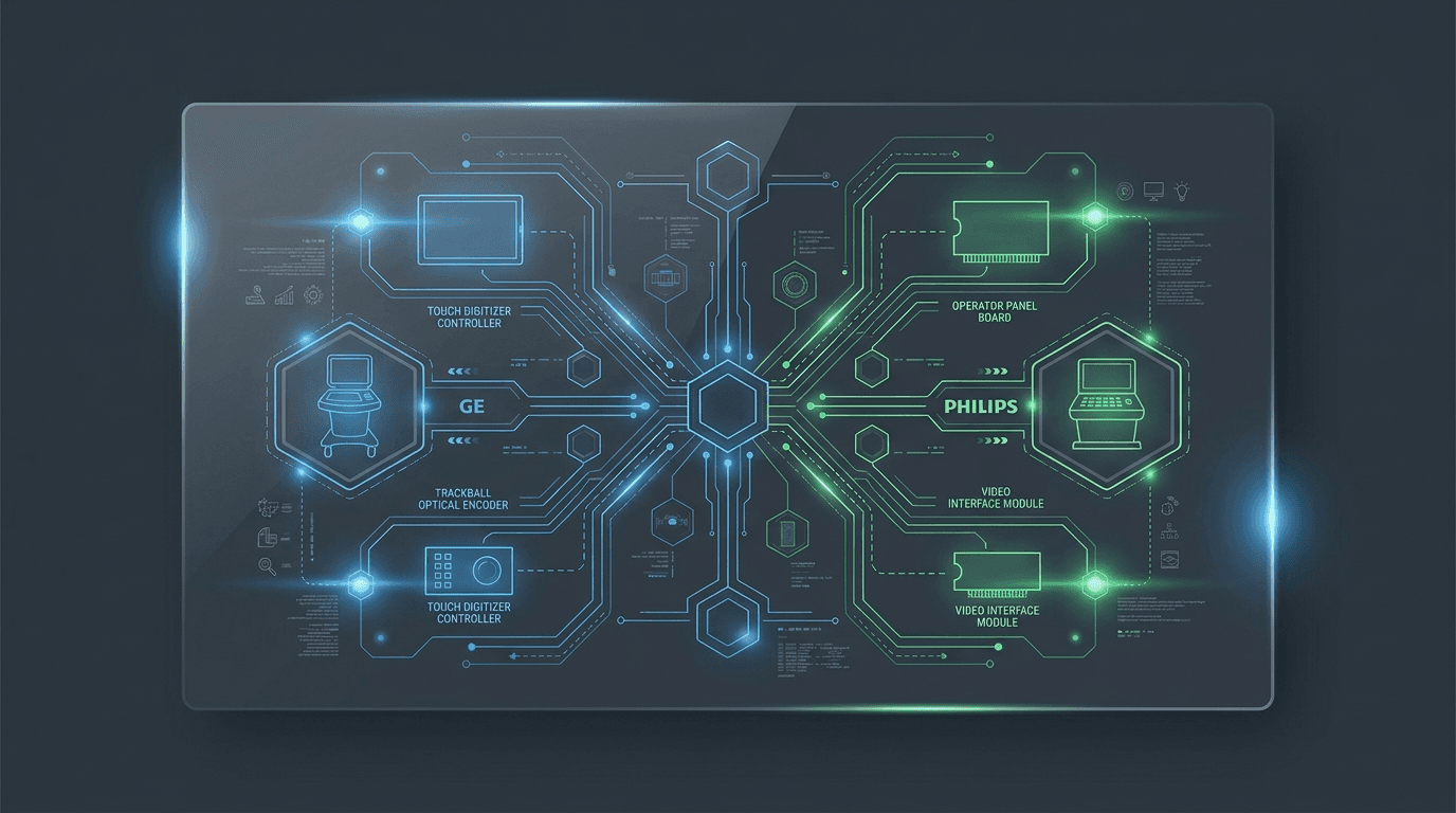
Introduction: Decoupling UI Subsystem Faults from Main Console Failures
In clinical ultrasound environments, the operator user interface—comprising the primary video display monitor, touch screen command panel, trackball navigation module, tactile mode buttons, and rotary gain encoders—serves as the critical interface between the clinician and the acoustic imaging engine. Consoles like the GE Voluson E8/E10 and LOGIQ E9/E10, Philips iU22/EPIQ 7, and Siemens Acuson S2000/Sequoia rely on sophisticated UI sub-assemblies to manage real-time scanning parameters.
UI components experience mechanical use, cleaning-chemical exposure and thermal load. Similar visible symptoms can come from the digitizer, controller, cable, display, host or power path, so replacing an entire operator panel before isolating the lane can add avoidable expense and downtime.
This diagnostic decision guide establishes a systematic four-lane classification framework for biomedical equipment technicians (BMETs) and independent service engineers to rapidly isolate operator panel, touch screen, trackball, and video interface board failures across multi-brand ultrasound fleets.
For complementary diagnostic isolation paths across console assemblies, service teams can consult our decision guides on GE Voluson/LOGIQ board symptom isolation, Philips iU22/EPIQ board symptom isolation, and Siemens Acuson board symptom isolation.
How do I classify an ultrasound UI fault into touch, control-panel/encoder, display/video, or system?
Field technicians encountering a user interface anomaly should categorize observed symptoms into four distinct functional hardware lanes:
- Lane 1: Touch Screen & Digitizer Subsystem. Symptoms: Touch screen fails to respond to touch inputs, registered touch coordinates are misaligned with displayed buttons, or specific touch zones are dead, while the primary B-mode image monitor and physical rotary knobs function normally. Suspected Hardware: Touch digitizer glass panel, touch controller board/IC (e.g., GE Touch 5207000-23 or 5776094), touch USB interface cable, or +5V/+12V touch power rail.
- Lane 2: Operator Control Panel, Trackball & Encoder Subsystem. Symptoms: Trackball cursor freezes, moves erratically, or loses axis sensitivity; rotary gain encoders skip values or fail to adjust gain; tactile mode keys (2D, Color, PW, Freeze) fail to respond; mode key LEDs fail to illuminate. Suspected Hardware: Trackball optical sensor assembly (e.g., TAS4719N / S9554921), rotary encoder bank (e.g., S5718726-2), control panel main PCBA (e.g., GE Control Panel 5207000-42 or 5776030-S), or panel interconnect ribbon harness.
- Lane 3: Video Display & Graphics Interface Subsystem. Symptoms: Primary monitor display flickers, shows vertical colored noise bands, or remains completely dark; secondary touch panel video drops out; display goes dark after boot logo while system continues to produce audio and respond to control panel inputs. Suspected Hardware: Main display LCD panel, LED backlight inverter board, IO video interface board (e.g., GE IO Video 9-1301-3707), display DVI/LVDS cable, or host GPU graphics card.
- Lane 4: Host System Control & Master Power Subsystem. Symptoms: Entire operator control panel remains dark with no LED backlighting, trackball illumination, or touch screen display; power button fails to initiate boot sequence. Suspected Hardware: Host PC motherboard, standby +5V/+12V power distribution board, or system master controller (SYSCON).
Table 1 details the diagnostic isolation steps, candidate assemblies, and safe verification tests across these four UI hardware lanes:
| UI Symptom Lane | Observed Console Symptom | Primary Candidate Board Assembly | Safe Verification / Isolation Test | Recommended Repair Action |
|---|---|---|---|---|
| Lane 1: Touch Screen | Touch panel unresponsive; glass intact; primary display normal | Touch Screen Controller / Digitizer | Perform touch screen calibration in service utility; check USB touch interface | Confirm the failed layer, then quote controller, digitizer or assembly repair |
| Lane 2: Control Panel | Trackball drift, dead axis, or erratic cursor jump | Trackball Optical Sensor Module | Inspect and clean only per the OEM procedure; compare with a known-good module where authorized | Confirm sensor, mechanics, cable and host input before selecting repair or replacement |
| Lane 2: Control Panel | Rotary gain knobs skipping values or non-responsive | Rotary Encoder Bank / Panel Board | Qualified personnel compare encoder output with the OEM procedure or a known-good channel | Confirm the encoder/circuit fault, then define component or assembly repair |
| Lane 3: Display Video | Primary monitor dark; backlight unlit; panel LEDs lit | Display Inverter / LCD Panel / Video Board | Connect external DVI monitor to rear panel video output port | Use the result with cable, EDID, backlight and internal-display checks before replacement |
| Lane 3: Display Video | Display flickers or shows video noise bands | IO Video Board / LVDS Cable | With power removed, inspect the connector/cable under the OEM service procedure | Confirm cable, panel and video-board contribution before choosing the assembly |
| Lane 4: Host Power | Entire operator panel dark; zero LED illumination | Standby Power Rail / Motherboard | Capture indicators and logs; qualified personnel follow the OEM power-good sequence | Isolate supply, distribution, host and panel loads before selecting a repair |
Source: Rongtao Medical engineering service database & multi-brand repair logs
When the touch screen is unresponsive but the image and knobs work, which part is at fault?
When touch input fails while the primary image and physical controls remain functional, the evidence narrows toward the touch path—digitizer, controller, cable, power, calibration or host interface. It still does not justify replacing a component before the OEM isolation checks.
In resistive and capacitive touch screen architectures utilized across GE Voluson E10, LOGIQ E9, and Philips EPIQ consoles, touch input signals flow from the glass touch digitizer through a flex ribbon connector to a dedicated touch controller board or controller IC. The touch controller digitizes touch coordinates and transmits them via an internal USB interface to the host operating system.
Diagnostic steps for isolating touch screen failures:
- Service Utility Touch Calibration: If authorized for the exact console, save the pre-test configuration and run the OEM calibration. Raw-point or offset behavior can narrow digitizer, controller and calibration hypotheses but does not prove the glass layer failed.
- USB Touch Interface Verification: Capture device-manager or service-log status. A missing controller or initialization code can involve power, cable, controller, host port or software; qualified personnel should follow the OEM isolation sequence before replacing a board.
- Glass Surface & Bezel Inspection: Inspect the perimeter seal for damage or fluid-ingress evidence. Clean only with the chemistry and method approved in the exact OEM IFU; do not apply generic isopropyl alcohol to an unknown lens, coating or gasket.
When the display flickers or goes black but the panel still responds, is it the display/video board or the GPU?
A black or flickering primary display monitor on a system that otherwise boots normally—indicated by illuminated control panel keys, active cooling fans, and audible audio feedback—can stem from four hardware elements: (1) Main LCD panel backlight assembly, (2) High-voltage LED backlight inverter rail, (3) Video interface board (e.g., GE IO Video Board PN 9-1301-3707), or (4) Host GPU graphics card.
To isolate the video fault without removing internal card cage assemblies, perform the External Display Isolation Test:
Where supported by the OEM procedure, connect a compatible known-good monitor using the specified output and resolution. A clean external image increases suspicion of the internal display, backlight, cable or routing path but does not prove every upstream GPU or software function is healthy. A missing or noisy external image likewise requires output-configuration, EDID, cable, host and video-generation checks before a motherboard conclusion.
Case Study Evidence: Three Documented UI Repair Case Analyses
To demonstrate practical diagnostic isolation and repair methods for UI subsystem failures, we analyzed three documented repair cases from Rongtao Medical's technical case archive 3:
- Case 1: Voluson E8 Touch Panel & Control Board Repair. Symptom: Touch screen digitizer was completely unresponsive, with no display output. Diagnostic Finding: Fault isolated to the touch-panel controller and the internal interconnect ribbon. Repair Resolution: Technicians replaced the touch controller, rebuilt the interconnect ribbon harness, and repaired the backlight rail. Outcome: Component-level rework fully saved the original control panel assembly.
- Case 2: Voluson S6 Control Panel Encoder Bank Repair. Symptom: Rotary knobs on the operator console stopped responding. Diagnostic Finding: A worn encoder in the operator panel. Repair Resolution: Technicians replaced the encoder bank, refitted the panel ribbons, and re-paired the control panel firmware with the system. Outcome: Successful subassembly repair without replacing the control panel.
- Case 3: Vivid E95 Video Interface Board Replacement. Symptom: Display flickered from boot. Diagnostic Finding: Fault isolated to the display / video subsystem, with the rest of the console responding normally. Repair Resolution: Technicians replaced the video interface board, renegotiated the EDID handshake, and confirmed display stability across all supported resolutions. Outcome: Targeted board assembly replacement.
Which control-panel, touch, trackball and display part numbers are available in tested stock (GE, Philips, Siemens)?
Rongtao Medical maintains 54 photo-backed UI, control panel, touch screen, trackball, and video interface board SKUs across 8 major OEM console brands in verified catalog stock 4.
Table 2 summarizes the distribution of verified UI part numbers by OEM brand:
| OEM Console Brand | Verified UI Catalog SKU Count | Primary Covered Part Types | Representative Verified OEM Part Numbers |
|---|---|---|---|
| GE Healthcare | 25 Part SKUs | Control panels, touch screens, trackballs, video boards, encoders | Control Panel 5207000-42, Touch 5207000-23 / 5776094, IO Video 9-1301-3707, Trackball TAS4719N |
| Philips Healthcare | 9 Part SKUs | Control panels, touch screens, trackballs | F-Version Control Panel 453561304221 (iU22), Control Panel 453561773636A (A50 / EPIQ), Trackball 700299-G017 (CX50) |
| Siemens Healthineers | 6 Part SKUs | Control panel boards, touch screens | Control Panel 10436217 (Acuson S2000), Control Panel 10437445 (SC2000), Touch Screen 11286732 (Sequoia) |
| Hitachi / Aloka | 7 Part SKUs | Control panels, touch screens | Control Panel EP573800BB (Arietta 60/70), Control Panel KB347443-A (HI VISION Avius), Control Panel UP-ALT12-A (Aloka ALPHA6) |
| Mindray Medical | 4 Part SKUs | Control panels, touch screens, trackballs | Control Panel 051-000663 (DC-8), Control Panel 051-001382-04 (M9), Trackball 023-001236-00 (DC-60/70) |
| Toshiba / Canon | 2 Part SKUs | Touch screens, control panels with trackball | Touch Screen BSM34-5530 (I600), Control Panel with Trackball BSM34-4188 (I600 / I800) |
| Esaote | 1 Part SKU | Control panel user interface module | Control Panel 9103491000 (MyLab Class C) |
Source: Rongtao Medical verified parts catalog
What electrical safety verification gate must be completed under IEC 60601-1?
Because user interface components—such as operator control panels, touch screens, and monitor housings—are touched continuously by clinical operators during patient examinations, post-repair electrical safety testing is a mandatory acceptance requirement.
In accordance with IEC 60601-1 and IEC 60601-2-37 safety standards 1, 2, service technicians completing control panel disassembly or video board replacement must perform the following safety handback checks prior to clinical release:
- Protective Earth Verification: Qualified personnel should record the applicable test points, current, limit and result for the complete system under the OEM/local electrical-safety procedure.
- Enclosure Touch Leakage Current Audit: Qualified personnel should use an appropriately specified medical electrical-safety analyzer and the applicable OEM/IEC test configuration, recording the limit and result for normal and required fault conditions.
- Liquid Ingress Integrity Check: Inspect touch screen bezel seals and trackball perimeter gaskets to ensure fluid resistance against clinical disinfectants.
For protocol details on conducting post-repair acceptance testing, see our guide on verifying ultrasound board part numbers and post-repair acceptance testing.
Where does Rongtao fit on UI/control/display repairs — and what should I send for a quote?
Rongtao Medical provides global biomedical engineering teams, ISOs, and equipment refurbishers with multi-brand repair services and tested replacement parts for ultrasound UI, control panel, touch screen, trackball, and video interface sub-systems.
Rongtao's public catalog dataset contains 54 photo-backed UI part records across 8 OEM brands 4. The company publishes a standard 5-to-8-business-day repair turnaround and a typical 90-day warranty; confirm applicability, test scope, live availability and exclusions for the quoted item 5.
To explore verified UI inventory or schedule a repair evaluation, visit our multi-brand parts catalog or contact our technical team via Rongtao Medical contact engineering.
When requesting a UI, control panel, touch screen, or video board repair or replacement quote, provide: (1) OEM console brand and exact model (e.g., GE Voluson E8 BT12, Philips iU22 F-Version), (2) Failing UI component description (e.g., touch screen digitizer, trackball assembly, IO video board), (3) Manufacturer part number and revision code, (4) High-resolution photos of component labels and connectors, (5) Observed hardware symptoms, and (6) Destination location for freight estimation.— Rongtao Medical Repair Handoff Protocol