
What does the Logiq E9 versus E10/E11 generation split mean for parts and repairs?
When clinical engineering departments and independent service organizations receive a service ticket for a down GE Logiq scanner, the single most critical diagnostic threshold is establishing whether the asset belongs to the legacy Logiq E9 platform or the successor Logiq E10 / Logiq E11 platform. Although both product lines carry the esteemed 'Logiq' brand banner and serve shared radiology and general-imaging clinical workflows, they represent two completely distinct electronic and computing architectures developed nearly a decade apart 1 8 Laptop LOGIQ e tickets — including catalog TX64 5436388 versus leftover 2404903 — are a different generation job and belong on the GE LOGIQ e versus LOGIQ E9 board path, not this cart GTX/ETX matrix.
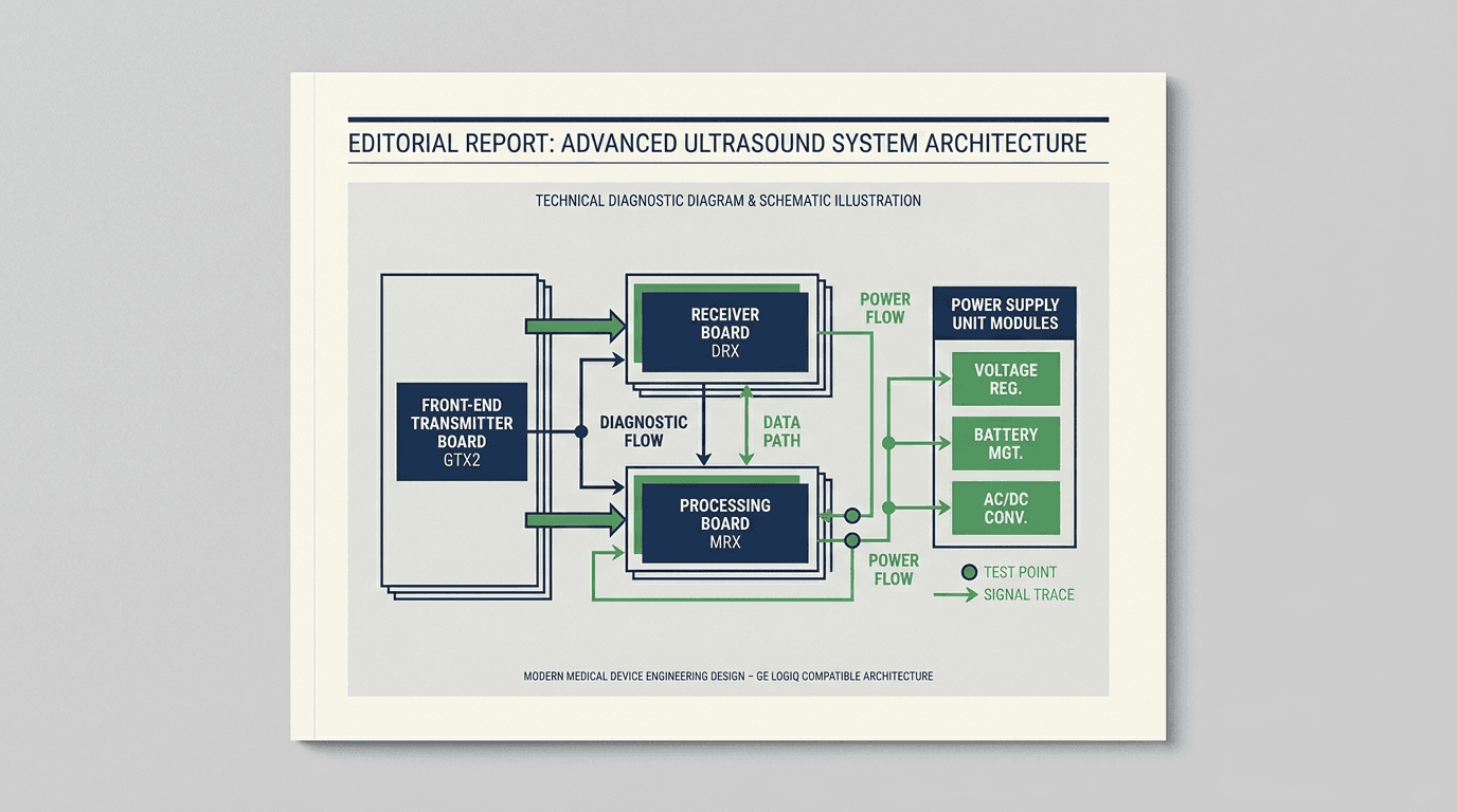
The GE Logiq E9 platform was originally cleared under FDA 510(k) K082185 on August 15, 2008 (Models 5205000 and 5205000-2) 1. Over its commercial lifespan—incorporating the BT2010 milestone (K092271), software revisions R1 through R6, and the XDClear / XDClear 2.0 iterations (K163077) 1—the E9 utilized a modular, distributed card cage. Acoustic transmission, echo reception, continuous-wave Doppler processing, and backplane routing were segregated into discrete printed circuit board assemblies (PCBAs) such as the GTX/GTX2 pulser board, DRX receiver board, MRX Doppler board, and GFI2 interface board 11. Computing tasks were hosted on an industrial PC motherboard (the catalog documents the AIMB-563 5155024 and PC 5380000-2 host boards), interfaced to the card cage through GE's proprietary back-end architecture 11.
In contrast, the GE Logiq E10 platform—cleared initially under FDA 510(k) K173555 in December 2017, and later expanding to include the Logiq E10s (K200119) and Logiq Fortis (K211524) with latest filings through 2025/2026 (K251985, K253366) 1—introduced GE's cSound software-based beamforming and GPU-accelerated reconstruction engine. In the E10/E11 architecture, hardware beamforming is consolidated into high-density transmit/carrier modules such as the ETX128 (5321216-4), ETX64, CRX2 Eagle receive assemblies (5503294) 6, ECB PC carrier boards (5589004-3), and next-generation BEP2/ECB2 host motherboards (5823770-2) 11.
Regulatory & nomenclature note on Logiq E11: In official FDA 510(k) premarket notification records, no distinct device named 'LOGIQ E11' appears as a standalone clearance; instead, the E11 is marketed and supported as an advanced system configuration within the overarching E10 platform family 1 8. Consequently, parts labeled in catalog inventories as Logiq E11 (such as ECB PC 5589004-3, ETX128 5321216-4, and PC Motherboard 5823770-2) belong to the E10 platform board generation, and OEM and dealer listings show this board generation across E10-series systems 6 11, but under no circumstances can they be installed into a Logiq E9 cart.
| Platform Family | Commercial Release Era | Key FDA 510(k) Clearances | Front-End Beamformer Architecture | Back-End Computing & Host PC | Cross-Generation Compatibility |
|---|---|---|---|---|---|
| Logiq E9 / E9 BT2010 | 2008 – 2012 | K082185 (Aug 2008), K092271 (Nov 2009 BT2010), K110943 (Jul 2011), K123564 (Dec 2012) 1 | Discrete card cage with separate transmit, receive, CW Doppler and interface boards — GTX2 (5201044 series), DRX (5301040 series), MRX CW (5393908), GFI2 (5161631); board revisions vary by production unit 11 | AIMB-563 motherboard (5155024), PC 5380000-2, BEP Small Power Board (5393801) 11 | Strictly isolated to E9 chassis. Requires exact part number and suffix matching across R-levels. |
| Logiq E9 XDClear / XDClear 2.0 | 2014 – 2016 | K142160 (Oct 2014), K152309 (Sep 2015 XDClear 2.0), K163077 (Nov 2016 XDClear 2.0) 1 | Same discrete card-cage architecture; the catalog also lists later board revisions GTX2.5 (5201044-7), DRX5 (5301040-5) and GTX-TLP 3.0 (GA200625-3) — FDA records carry no R-level-to-board mapping, so the board label decides 11 | AIMB-563 / PC host platform with BEP Small Power Board (5393801) 11 | No assumed interchange across E9 hardware generations — match part number and revision suffix, and confirm with the supplier. |
| Logiq E10 / Logiq E10s / Logiq E11 | 2017 – Present | K173555 (Dec 2017 E10), K200119 (Apr 2020 E10s), K200158 (Apr 2020 E10), K211488 (Sep 2021) 1 | cSound software architecture: ETX128 (5321216-4), ETX64, CRX2 Eagle (5503294), DA192 (8804400-2) 6 11 | ECB carrier board (5589004-3), BEP2 PC motherboard (5823770-2), GPU-accelerated cSound reconstruction host 11 | No catalog-verified interchange with Logiq E9. E10-series configurations share platform boards — verify exact part number and suffix. |
| Logiq Fortis (E10 Platform Sibling) | 2021 – Present | K211524 (Aug 2021 E10s/Fortis), K231989 (Nov 2023), K251963 (Oct 2025), K253366 (Jan 2026) 1 | Compact cSound architecture: shared digital beamforming processing and high-density front-end | Consolidated industrial host computer within the shared E10-family platform | Shares the E10/E10s platform family; no interchange with E9 parts. |
Source: Synthesized from U.S. FDA 510(k) premarket notification records, GE HealthCare commercial portfolios, and Rongtao Medical hardware inventory data
Safety and scope boundary: The troubleshooting workflows, pinouts, and test protocols in this report are intended exclusively for qualified biomedical equipment technicians (BMETs) and clinical service personnel working on completely de-energized systems. Disconnect AC mains power before removing covers or reseating cards. Never bypass cabinet safety interlocks, and never return a repaired ultrasound system to clinical patient scanning without comprehensive electrical safety (IEC 60601-1) and phantom image quality acceptance testing.
Which board family does my Logiq E9 symptom point to: transmit (GTX/GTX2), receive (DRX), or processing (MRX, GFI2)?
The acoustic front end of the GE Logiq E9 is a high-precision multi-channel transceiver system housed inside the scanner's main card cage. When imaging anomalies occur during clinical examinations, technicians can rapidly narrow the root cause by evaluating whether the defect is isolated to a single transducer, shared across all probe ports, or restricted to a specific imaging modality (such as 2D B-Mode, Color Flow, or Continuous Wave Spectral Doppler) 10 11.
The signal processing pipeline moves through four primary board families 11 12:
- GTX / GTX2 Transmitter Pulser Boards: The high-voltage pulse generators (e.g.,
GTX2.4 5201044-3,GTX2.5 5201044-7, andGTX-TLP 3.0 GA200625-3) convert low-voltage digital timing triggers into +/- high-voltage pulses that excite transducer piezoelectric elements 11. A failed MOSFET pulser bank or blown high-voltage protection fuse on a GTX board results in total image blackout ('no echo') across all probes or severe acoustic penetration loss. - DRX Digital Receiver Boards: The low-noise analog amplification and digitization stage (e.g.,
DRX 3.1 5301040-4,DRX5 5301040-5, orDRX6 5301160-6) receives microvolt-level acoustic echoes from the patient, applying time-gain compensation (TGC), anti-aliasing filtering, and analog-to-digital conversion (ADC) 11. A failing DRX board produces vertical dark bands, static snow, or horizontal line artifacts across the entire sector image on every connected probe. - MRX Continuous Wave (CW) Doppler Processing Board: Dedicated auxiliary processing (e.g.,
MRX CW 5393908) handles high-velocity cardiovascular and vascular spectral Doppler demodulation 11. When 2D B-mode and Color Doppler display crisp anatomy but Continuous Wave (CW) or Pulsed Wave (PW) Doppler produces flat-line traces, severe background hum, or system crashes upon activating the Doppler cursor, the MRX CW board is the primary suspect 12. - GFI2 Front-End Interface Board: Acting as the master bus coordinator and transducer interface (e.g.,
GFI2 5161631), this assembly controls transducer select relays, ID EEPROM communication, high-voltage sequencing, and front-to-backplane handshakes 11. Failures trigger 'Probe Not Recognized' errors across all probe ports or front-end bus initialization timeouts during system POST.
| Observed Clinical Symptom | Scope & Modality Dependency | Primary Hardware Domain | Suspect Assembly & Part Number | Bench Isolation & Swap Protocol | Documented Resolution |
|---|---|---|---|---|---|
| Total Blackout / No Echo on All Probes | Affects 2D, Color, and Doppler across all probe ports simultaneously | High-Voltage Transmit Pulsing / Front-End HV Supply | GTX2.4 (5201044-3) / GTX2.5 (5201044-7) 11 | Verify the high-voltage transmit rails from the PSU against service documentation. If voltages are nominal, inspect the pulser bank driver ICs and high-voltage protection components. | Component-level pulser IC and MOSFET rebuild on GTX2 board; 48-hour real-machine test (5–8 day typical turnaround) 11 12. |
| Vertical Dead Band / Dark Sector Stripe | Permanent vertical stripe visible on all probes and across all presets | Multi-Channel Analog Receive & Digitization | DRX 3.1 (5301040-4) / DRX5 (5301040-5) 11 | Swap probe to alternate port to rule out transducer connector pin damage. If dead band persists at identical sector position, isolate to the DRX channel ADC bank. | Rework failed pre-amplifier/ADC channel array on DRX board; calibrate channel gain uniformity 11. |
| CW Doppler Failure / Audio Buzzing | 2D B-mode is normal; spectral Doppler freezes or outputs static noise upon cursor activation | Continuous Wave Doppler Demodulation | MRX CW Doppler Board (5393908) 11 | Execute system service diagnostic CW self-test. Inspect MRX board for thermal discoloration near analog filter ICs. | Component rework on MRX CW demodulator and filter circuitry; verified in documented legacy repair notes 12. |
| All Probes Unrecognized / 'Connect Probe' Error | System boots but fails to detect any transducer plugged into any of the 4 ports | Transducer Interface & Bus Multiplexing | GFI2 Interface Board (5161631) 11 | Inspect probe port pins for physical bending. Check +5V ID bus supply rail on GFI2 interface board. | Rebuild GFI2 interface logic and probe multiplexing relay drivers; restore 1-wire ID bus communication 11. |
| Severe Image Noise / Sparkle Artifacts | Dynamic snow/grain across image that scales with depth gain | Front-End Power Filtering / Ground Return | DRX Receiver or Backplane Power Decoupling | Disconnect ambient AC peripherals. Check the DRX low-voltage analog supply rails for high-frequency switching ripple with an oscilloscope. | Replace degraded low-ESR filter capacitors and linear regulators on DRX receiver assembly 11. |
Source: Synthesized from Rongtao Medical legacy repair archives, catalog part records, and standard qualified-technician bench practice
For readers seeking a broader technical breakdown of acoustic wave transmission physics and channel multiplexing, consult our companion reference on beamformer and front-end board failures.
How do I diagnose Logiq E9 power and boot failures across the three PSU revisions and BEP board?
Power delivery on the GE Logiq E9 is a multi-tier conversion hierarchy engineered to isolate sensitive analog ultrasound electronics from the noisy electrical switching environment of the PC host computer and cooling fans 10. When an E9 fails to turn on or experiences sudden power shutdowns during boot, field engineers must distinguish between primary AC/DC power supply failures, secondary rail short circuits, and host computer power distribution faults 11.
The Logiq E9 power subsystem centers on two primary hardware assemblies 11:
- Main AC/DC Power Supply Unit (PSU): Mounted in the lower chassis, the main PSU converts AC mains into standby and system DC rails plus the high-voltage rails that drive the acoustic front end. In Rongtao's verified catalog, the E9 main PSU exists across three documented part numbers:
5205052-3,5205052-10, and5433408-2111. Neither the catalog nor the FDA records map these part numbers to R-levels or marketing generations — read the part number from the supply's own label and system documentation before ordering a replacement. - BEP Small Power Board (GA200876 / 5393801): Located inside or adjacent to the Back-End Processor (BEP) computer enclosure, this specialized DC-DC converter board (
GA200876 / 5393801) takes bulk DC from the main PSU and provides tightly regulated, low-noise sub-rails directly to the AIMB-563 motherboard, CPU VRMs, and storage drives 11. A degraded capacitor or failed switching regulator on the BEP small power board can cause the system to briefly spin its fans and immediately power down, mimicking a catastrophic main PSU failure.
| Observed Power Symptom | Indicator Status & Fan Behavior | Primary Fault Domain | Suspect Assembly & Part Number | Diagnostic Isolation & Test Procedure | Recommended Repair Action |
|---|---|---|---|---|---|
| Total Dead System (No Standby) | No standby LEDs on console; fans completely stationary; no relay click on breaker engage | AC Mains Inlet / Main PSU Primary Stage | Main Power Supply Unit (5205052-3 / 5205052-10 / 5433408-21) 11 | MANDATORY RECALL CHECK: Inspect system power cord for internal conductor breakage (Recall Z-2983-2018) 2. Check rear AC breaker and primary internal fuses with DMM. Measure +5VSB standby pin on main harness. | Replace defective power cord if suspect. Rebuild main PSU primary switching stage, PFC circuit, and standby regulator (5-8 day TAT) 11. |
| Power Drop on Boot (Trips within seconds) | Fans spin briefly; console lights flash once; main power cuts off immediately | Secondary DC Overcurrent / Shorted Card in Cage | Front-End Board (GTX/DRX) or BEP Small Power Board (5393801) 11 | Disconnect AC power. Extract all front-end cards (GTX, DRX, MRX, GFI2) from the card cage. Power on with cage empty. If system stays powered, insert cards one by one to find the clamping board. | Isolate shorted tantalum capacitor or MOSFET on the clamping card; rebuild BEP small power board (5393801) if power drop persists with empty card cage 11 12. |
| Continuous Auto-Reboot Loop | System powers on, fans run, displays initial BIOS or GE splash, resets, and repeats indefinitely | BEP Host Power Rail Instability / Corrupt CMOS | BEP Small Power Board (5393801) or Host Motherboard (5155024) 11 | Measure DC voltage ripple on +3.3V, +5V, and +12V motherboard ATX headers during boot. Check CR2032 CMOS battery voltage on AIMB-563 board. | Rebuild voltage regulator circuitry on BEP small power board; replace CMOS battery and reflash BIOS EEPROM 11. |
| Intermittent Shutdown During Scanning | System scans normally for an extended session, then abruptly shuts down without error dialogue | Thermal Overload / PSU Secondary Capacitor Degradation | Main Power Supply Unit (5433408-21) Cooling Fan / Capacitors 11 | Inspect lower PSU exhaust fans for dust clogging or seized bearings. Monitor internal PSU heatsink thermistor telemetry in service utility. | Full electrolytic capacitor refresh and replacement of high-grade ball-bearing cooling fans in main PSU assembly 11. |
Source: Synthesized from FDA enforcement data, Rongtao Medical legacy repair records, and catalog part data
For deeper analysis of DC rail sequencing, over-voltage protection (OVP) clamping, and bench test protocols, refer to our foundational report on ultrasound power-supply failure and boot-loop diagnosis. Also review documented historical cases such as our Logiq E9 frequent crashes service note 12.
When does a host PC or control path fault point to AIMB-563 motherboards or the control panel?
The Back-End Processor (BEP) is the computational nerve center of the Logiq E9. It runs GE's ultrasound application software, managing user inputs, image reconstruction, digital measurement calculations, DICOM connectivity, and user interface displays 5 10.
When an E9 hangs during boot, freezes mid-scan, or experiences non-responsive operator controls, the fault isolates across four key subsystem assemblies 11:
- Host Computer Motherboards: Across E9 production runs, two primary industrial motherboards are documented: the
AIMB-563 5155024and thePC 5380000-211. Motherboard failures typically manifest as BIOS POST halts, blue-screen (BSOD) stop errors, USB peripheral dropouts, or SATA drive communication loss caused by aged chipset solder joints or degraded solid capacitors. - Operator Control Panel (5207000-42): The primary operator console (
5207000-42) houses the alphanumeric keys, rotary encoders, TGC slide potentiometers, and trackball controller 11. Physical keyboard freezes, erratic trackball tracking, or 'Keyboard Out of Control' alarms isolate to the internal USB microcontroller or worn potentiometer contact strips on this assembly. - Touch Screen Assembly (5207000-23): The secondary touch-screen interface (
5207000-23) displays contextual preset menus, probe selections, and annotation keys 11. Symptoms such as dead touch zones, uncalibrated touch coordinates, or backlight failure isolate to the resistive/capacitive digitizer overlay, internal inverter, or display controller. - Back-End Video / I/O Interface (5141000-3): In earlier E9 revisions, the
IO 5141000-3 (old version)and GE's5207000-60Main Board with SMC Hub Video Board 5 11 manage external monitor DVI/VGA outputs, auxiliary video inputs, and peripheral foot-switch signals. Blank external monitors with active touch screens isolate to this I/O video hub.
For further exploration of back-end image reconstruction and host computer architectures, see our detailed guide to back-end and image-processing board failures.
Which Logiq E10/E11 boards (ETX128, ECB, DA192) swap within the platform — and what never crosses to an E9?
As independent service organizations expand their capabilities to support newer general-imaging fleets, managing parts for the Logiq E10 and Logiq E11 requires an exact understanding of GE's next-generation modularity. Unlike the E9's separate pulser and receiver cards, the E10/E11 platform consolidates electronic functions into high-density assemblies 6 8.
Key assemblies verified in Rongtao's technical inventory and OEM documentation include 6 11:
- ETX128 / ETX64 Transmit Boards (5321216-4): High-density pulser assemblies responsible for multi-channel acoustic pulse synthesis. The
ETX128 5321216-4transmit board is a catalog-listed E11 row, and dealer listings show ETX-generation transmit boards across E10-series chassis — confirm the exact variant (ETX64, ETX128 or the separately dealer-listed ETX192) and revision from the board label before ordering 11. - ECB PC Carrier Board (5589004-3): Known in the industry as the 'Eagle Carrier Board' 6, this assembly (
5589004-3) interfaces high-speed PCIe channels between the front-end card cage and the central host processor. It serves as the primary backbone for both Logiq E10 and E11 systems 11. - BEP2 / PC Motherboard (5823770-2): The next-generation host motherboard (
5823770-2) powers the cSound reconstruction software, hosting high-performance multi-core processors and GPU accelerators 11. - DA192 Transducer Interface Board (8804400-2): High-density probe connection and pin routing module (
8804400-2) for the platform's multi-pin transducer sockets 11.
| Board Assembly Name | Part Number / ID | Functional Role in System | Logiq E10 Compatibility | Logiq E11 Compatibility | Logiq E9 Interchangeability |
|---|---|---|---|---|---|
| ETX128 Transmit Board | 5321216-4 11 | High-density digital transmit module | ETX-generation transmit boards appear across E10-series configurations — verify variant | Catalog-listed for E11 (5321216-4) | INCOMPATIBLE (Different bus & form factor) |
| ECB PC Carrier Board (Eagle) | 5589004-3 11 | High-speed bus carrier & bridge | OEM/dealer-listed as the E10 'Eagle' carrier | Catalog-listed for E11 (5589004-3) | INCOMPATIBLE (different bus and form factor) |
| PC Motherboard (BEP2) | 5823770-2 11 | cSound CPU host & reconstruction engine | Platform host across the E10 series — verify assembly | Catalog-listed for E11 (5823770-2) | INCOMPATIBLE (different host architecture generation) |
| DA192 Probe Interface | 8804400-2 11 | High-density transducer socket interface | Catalog-listed for E10 (8804400-2) | Used across the platform — verify configuration | INCOMPATIBLE (Physical connector mismatch) |
| CRX2 Eagle Receive Assembly | 5503294 6 | High-density multi-channel digital receiver | GE Service Shop listing (E10 family) | E10-family receive generation — verify assembly | INCOMPATIBLE (E9 uses discrete DRX boards) |
Source: Synthesized from GE HealthCare Service Shop listings, third-party dealer documentation, and Rongtao Medical parts catalog records
Read the compatibility cells above as evidence tiers, not blanket approvals. The E10-column entries rest on Rongtao catalog rows plus GE Service Shop and dealer listings, and GE built the E10-series transmit generation in multiple variants (ETX64, ETX128, and the separately dealer-listed ETX192). The exact board variant and revision suffix must be confirmed from the label and with the supplier before any order. What the combined evidence does establish is the negative rule that matters most when buying parts: none of these E10/E11 assemblies substitutes for a Logiq E9 board.
Is the GTX-TLP.192 board shared across Logiq E9 and Vivid E9 — and how do I verify before ordering?
A frequent question among multi-brand ultrasound service teams is whether boards from GE's cardiovascular flagship—the Vivid E9 / Vivid E95—can be cross-installed into the radiological Logiq E9. Because both systems share common mechanical cart ergonomics and were developed during adjacent engineering cycles, several sub-assemblies look identical externally 10 11.
Based on verified ground truth in Rongtao's parts catalog, exactly one major front-end board is catalog-listed under both model families: the GTX-TLP.192 GA200726 board 11. It appears in the catalog under both the LOGIQ E9 SKU (logiq-e9-gtx-tlp-192-ga200726) and the VIVID E9 E80 E95 SKU (vivid-e9-e80-e95-gtx-tlp-ga200726-2) 11. This cross-system capability is independently corroborated by Rongtao's legacy repair archive, which documents component-level repair service for the 'GE Logiq E9/Vivid E9 GTX-TLP192 Board (GA200726)' and the shared 'GFI2' interface board 12.
However, technicians must exercise extreme caution with other look-alike assemblies 11:
- Vivid GRX64 / GRX128 vs Logiq DRX: The Vivid E9 uses dedicated
GRX64 GA200300-5andGRX128 GA200295-5receiver boards tailored for high-frame-rate cardiac phased array transducers 11. These do not swap with the Logiq E9'sDRX 3.1 5301040-4orDRX5 5301040-5general-imaging receiver boards. - Main Power Supplies: The Vivid E9 uses power supply assemblies such as
GA200730andGA200730-511, which carry different internal harness pinouts and high-voltage rail current limits compared to the Logiq E9's5205052-3/-10and5433408-21supplies 11. - Control Panels & Keyboards: The Vivid E9 operator surface contains dedicated cardiac measurement keys, Doppler steer controls, and specialized continuous-wave presets that differ fundamentally from the Logiq E9's radiology-centric control panel (
5207000-42) 11.
The golden rule of GE parts procurement: Never order an ultrasound PCBA based on visual appearance or scanner model name alone. Always inspect the white manufacturer barcode sticker on the physical circuit board, recording the full part number and revision suffix before ordering. For incoming quality control criteria, review our checklist for ultrasound board part-number verification and acceptance.
Why does the board label and revision suffix decide compatibility across E9 R1–R6 and XDClear?
Throughout the eight-year manufacturing run of the Logiq E9, GE implemented iterative hardware revisions designated in service software as R-levels (Release 1 through Release 6) and commercially packaged as the Logiq E9 XDClear and Logiq E9 XDClear 2.0 1 10. When an engineering update was introduced, GE often revised circuit board layouts, updated onboard FPGA programmable logic, or altered power decoupling networks 11.
This internal evolution is directly reflected in manufacturer part number revision suffixes 11:
- GTX2 Pulser Suffixes: The GTX2 transmitter board family is documented across the
GTX2.3 5201044-2,GTX2.4 5201044-3andGTX2.5 5201044-7revisions in the catalog and the legacy service archive 11 12. The revision suffix — not the scanner's R-level name — determines the correct replacement; a mismatched revision risks front-end firmware mismatch or degraded acoustic performance, so confirm the label against the chassis configuration with your supplier before ordering. - DRX Receiver Suffixes: The digital receiver board is catalog-documented in
DRX 3.1 5301040-4,DRX5 5301040-5andDRX6 5301160-6revisions; which revision a given chassis carries must be read from the board label, because neither the catalog nor FDA records map R-levels to receiver revisions 11. - Main Power Supply Suffixes: As detailed previously, the main PSU exists in the three catalog-documented part numbers
5205052-3,5205052-10and5433408-21— identified by label, not by R-level 11.
| Catalog Item ID | Listed Model Family | Part Description & Board Designation | Manufacturer Part Number | Verified Platform Role |
|---|---|---|---|---|
logiq-e9-gtx2-4-5201044-3 | LOGIQ E9 | GTX2.4 Ultrasound Transmit Board | 5201044-3 | E9 transmit pulser board 11 |
logiq-e9-gtx2-5-5201044-7 | LOGIQ E9 | GTX2.5 Ultrasound Transmit Board | 5201044-7 | E9 transmit pulser board (later revision) 11 |
logiq-e9-gtx-tlp-192-ga200726 | LOGIQ E9 | GTX-TLP.192 Transmit Board | GA200726 | Shared pulser with Vivid E9/E80/E95 11 |
logiq-e9-drx-3-1-5301040-4 | LOGIQ E9 | DRX 3.1 Digital Receive Board | 5301040-4 | E9 digital receiver board 11 |
logiq-e9-drx5-5301040-5 | LOGIQ E9 | DRX5 Digital Receive Board | 5301040-5 | E9 digital receiver board (later revision) 11 |
logiq-e9-mrx-cw-5393908 | LOGIQ E9 | MRX CW Doppler Processing Board | 5393908 | Continuous Wave Doppler processor 11 |
logiq-e9-gfi2-5161631 | LOGIQ E9 | GFI2 Front-End Interface Board | 5161631 | Front-end bus & probe port interface 11 |
logiq-e9-bep-small-power-board-ga200876-5393801 | LOGIQ E9 | BEP Small Power Board | 5393801 | Host PC local DC voltage regulator 11 |
logiq-e9-power-supply-5205052-3 | LOGIQ E9 | Main Power Supply Unit (5205052-3) | 5205052-3 | E9 main AC/DC power supply 11 |
logiq-e9-power-supply-5205052-10 | LOGIQ E9 | Main Power Supply Unit (5205052-10) | 5205052-10 | E9 main AC/DC power supply 11 |
logiq-e9-power-supply-5433408-21 | LOGIQ E9 | Main Power Supply Unit (5433408-21) | 5433408-21 | E9 main AC/DC power supply 11 |
logiq-e9-motherboard-aimb-563-5155024 | LOGIQ E9 | Industrial Host Motherboard AIMB-563 | 5155024 | BEP industrial PC motherboard 11 |
logiq-e9-control-panel-5207000-42 | LOGIQ E9 | Operator Control Panel Assembly | 5207000-42 | Primary user interface console 11 |
logiq-e9-touch-screen-5207000-23 | LOGIQ E9 | Touch Screen Display Assembly | 5207000-23 | Secondary touch user interface 11 |
logiq-e10-da192-8804400-2 | LOGIQ E10 | DA192 Probe Interface Board | 8804400-2 | E10 high-density transducer socket 11 |
logiq-e11-etx128-5321216-4 | LOGIQ E11 | ETX128 Digital Transmit Board | 5321216-4 | 128-ch pulser for E10/E11 platform 11 |
logiq-e11-ecb-pc-5589004-3 | LOGIQ E11 | ECB PC Carrier Board (Eagle) | 5589004-3 | PCIe carrier for E10/E11 platform 11 |
logiq-e11-pc-motherboard-5823770-2 | LOGIQ E11 | PC Motherboard (BEP2) | 5823770-2 | cSound CPU host for E10/E11 platform 11 |
Source: Extracted from Rongtao Medical verified parts catalog ground truth. Catalog IDs serve as identity anchors; stock turns, so availability routes to the live quote flow.
The catalog also carries family rows not shown above — the PC host board (5380000-2), the old-version I/O board (5141000-3), the GTX-TLP 3.0 (GA200625-3) transmit board and the DRX6 (5301160-6) receiver. Catalog rows establish part identity and listed model context, not live stock; availability changes, so route sourcing questions to the live parts catalog and the quote flow.
What safety recall gates must I check before Logiq E9/E10 power or TEE servicing?
Before condemning electronic circuit boards or executing hardware swaps, clinical engineering teams must verify whether observed scanner misbehaviors are tied to known historical safety recalls. Reviewing regulatory records from the U.S. FDA Medical Device Recalls database reveals three critical historical enforcement actions affecting the Logiq family 2 3 4:
- Logiq E9 System-Side Power Cord Break (Recall Z-2983-2018): Initiated on March 22, 2018, this recall (root cause recorded by FDA as component design/selection) addressed a defect where the system side of the AC mains power cord could break and expose live electrical conductors, presenting an immediate electrical shock hazard 2. When an E9 presents with intermittent power loss or no power, technicians must physically inspect the AC power cord strain relief and conductors before diagnosing a main PSU failure.
- Logiq E10 TEE Probe Over-Temperature Condition (Recall Z-0588-2019): Initiated on September 14, 2018, this action (Root Cause: Process change control) covered Logiq E10 systems (Model #530000E10) in which an over-temperature condition on the trans-esophageal (TEE) probe could go undetected, creating a possible patient burn-injury risk 3. When servicing an E10 with a TEE history, confirm with current GE service documentation that the applicable temperature protections are in place.
- Logiq E9 Software R3.1.0/R3.1.1 Patient Data Integrity (Recall Z-0705-2012): Initiated on January 3, 2012, this software correction (root cause recorded by FDA as software design) addressed an issue in which a user could see an image or data belonging to a different patient 4. This historical event demonstrates that software revision stability must be confirmed before attributing data crashes to hardware memory boards.
Regulatory context & methodology note: All three enforcement actions are officially classified by the FDA as Terminated, indicating that corrective field actions and safety notices were completed. Recall records describe specific corrective events and do not measure overall device failure incidence or comparative brand reliability. Furthermore, an analysis of FDA MAUDE passive-surveillance records for 2025 across 2,888,003 scanned adverse event records yielded exactly 1 brand mention for the Logiq E9 and 0 for the E10/E11. Because passive surveillance lacks total installed-base denominators, report counts cannot be used to establish device failure rates.
| 510(k) Number | Cleared Device Name | Applicant / Manufacturer | FDA Decision Date | Platform Generation Role |
|---|---|---|---|---|
| K082185 | GE LOGIQ E9 DIAGNOSTIC ULTRASOUND SYSTEM, MODELS 5205000, 5205000-2 | GE Medical Systems Ultrasound | 2008-08-15 | Original Logiq E9 commercial platform baseline 1 |
| K092271 | GE LOGIQ E9 BT2010 DIAGNOSTIC ULTRASOUND SYSTEM, MODEL 5205000-3, 5205000-4 | GE Healthcare | 2009-11-17 | BT2010 software & hardware upgrade package 1 |
| K110943 | LOGIQ E9 | GE Healthcare | 2011-07-22 | Mid-generation E9 family update 1 |
| K123564 | LOGIQ E9 DIAGNOSTIC ULTRASOUND SYSTEM | GE Healthcare | 2012-12-18 | E9 family update (2012) 1 |
| K142160 | LOGIQ E9 DIAGNOSTIC ULTRASOUND SYSTEM | GE Healthcare | 2014-10-10 | E9 family update (2014) 1 |
| K152309 | LOGIQ E9, LOGIQ E9 XDClear 2.0 | GE Medical Systems Ultrasound | 2015-09-14 | XDClear 2.0 generation introduction 1 |
| K163077 | LOGIQ E9, LOGIQ E9 XDClear 2.0 | GE Medical Systems Ultrasound | 2016-11-17 | Final major Logiq E9 family 510(k) clearance 1 |
| K173555 | LOGIQ E10 | GE Healthcare | 2017-12-20 | Original Logiq E10 cSound platform clearance 1 |
| K200119 | LOGIQ E10s | GE Medical Systems Ultrasound | 2020-04-01 | Logiq E10s variant clearance 1 |
| K200158 | LOGIQ E10 | GE Medical Systems Ultrasound | 2020-04-17 | E10 platform update 1 |
| K211524 | LOGIQ E10s, LOGIQ Fortis | GE Healthcare | 2021-08-27 | Introduction of Logiq Fortis into platform family 1 |
| K211488 | LOGIQ E10 | GE Healthcare | 2021-09-10 | E10 platform update 1 |
| K231966 | LOGIQ E10 | GE Medical Systems Ultrasound | 2023-11-07 | E10 platform update 1 |
| K231989 | LOGIQ E10s, LOGIQ Fortis | GE Medical Systems Ultrasound | 2023-11-07 | E10s / Fortis family update 1 |
| K251963 | LOGIQ E10s | GE Medical Systems Ultrasound | 2025-10-29 | E10s family update 1 |
| K251985 | LOGIQ E10 | GE Medical Systems Ultrasound | 2025-10-29 | E10 family update 1 |
| K253366 | LOGIQ Fortis | GE Medical Systems Ultrasound | 2026-01-07 | Logiq Fortis family update 1 |
Source: Computed from U.S. FDA 510(k) Premarket Notification Database records. Exact filters: device_name containing LOGIQ E9, LOGIQ E10, LOGIQ E10s, or LOGIQ Fortis.
Should I repair the board, buy a tested replacement, or plan migration off the E9 platform?
When a Logiq E9 experiences a major electronic sub-system breakdown, healthcare technology managers face a strategic three-way decision: (1) repair the original board at the component level, (2) procure a tested exchange/replacement board, or (3) retire the scanner and migrate to a modern platform (Logiq E10 / Fortis) 7 11.
Evaluating these pathways requires weighing fleet clinical demand, remaining scanner economic life, and parts availability 7:
- Component-Level Board Repair (Recommended for Out-of-Warranty Fleets): For known circuit failures on high-value assemblies (such as GTX2 pulser MOSFETs, DRX receiver channel ICs, MRX CW demodulators, or PSU capacitor degradation), component-level repair preserves the original calibrated PCBA, avoids software re-licensing hurdles, and delivers standard 5–8 business-day turnaround with typical 90-day warranty terms at substantial cost savings compared to OEM replacements 11.
- Tested Replacement / Advance Exchange: When downtime must be resolved within 24–48 hours, procuring a pre-tested, revision-matched replacement board from a qualified supplier is the fastest route. The replacement must be backed by documented 48-hour live ultrasound chassis testing 11.
- Platform Migration: If an early-generation E9 (R1–R3) suffers simultaneous back-end motherboard, power supply, and card cage degradation, the cumulative repair cost and aging acoustic performance may justify planning a phased migration to an E10 or Fortis platform 8. To verify current OEM support status, consult GE HealthCare's Lifecycle Tracker 7.
| Decision Pathway | Optimal Clinical & Asset Scenario | Typical Turnaround Time | Economic & Capital Impact | Key Engineering Risk & Quality Gate |
|---|---|---|---|---|
| Component-Level Board Repair | Single board failure (GTX2, DRX, MRX, PSU); scanner chassis is mechanically sound and clinically active | Standard 5–8 business days 11 | Low cost; preserves original board calibration and software pairing | Requires supplier with real-system test capability and 48-hour burn-in protocols 11. |
| Tested Pre-Owned Replacement | Urgent emergency downtime; severely burned board with charred multi-layer PCB traces | Stock- and supplier-dependent | Moderate cost; faster turnaround than bench rework | Must verify exact revision suffix matching on board barcode label 11. |
| Platform Migration (Logiq E10 / Fortis) | Multiple cascading failures across power, host PC, and card cage on aging R1/R2 chassis | Driven by procurement and installation timeline | High capital expenditure; requires new probe inventory and user training | E9 transducers and boards do not transfer to E10 cSound platform 1 8. |
Source: Synthesized from ISO fleet management guidelines and Rongtao Medical service engineering protocols
For broader commercial decision frameworks, explore our in-depth analysis of ultrasound board repair versus replacement and our practical multi-brand board repair RFQ template.
Where does Rongtao fit — and where does it not?
Rongtao Medical operates as an independent, ISO 13485:2016 and ISO 9001:2015 certified technical service and supply center specializing in multi-brand medical ultrasound hardware. To maintain complete transparency with our hospital and ISO partners, we clearly define our technical capabilities and operational boundaries 11:
Where Rongtao Fits:
- Component-Level Circuit Board Repair: Precision micro-soldering, IC replacement, trace repair, and capacitor rebuilding for GE Logiq E9, E10, and E11 circuit boards (GTX2, DRX, MRX, GFI2, BEP power boards, and main PSUs) 11.
- 48-Hour Real-Machine Testing: Every repaired or supplied board undergoes a rigorous 48-hour burn-in and functional test cycle inside an actual ultrasound system before dispatch 11.
- Standardized Service Terms: Typical 5–8 business-day repair turnaround and a standard 90-day warranty (extended warranty available on request) 11.
- Global Bonded-Zone Logistics: Fast, compliant worldwide shipping via DHL, FedEx, and UPS with full customs documentation from our Guangzhou technical facility 11.
- Transducer Repair Services: Comprehensive probe lens replacement, acoustic cable rebuilding, and strain relief repair via our dedicated probe repair service.
Where Rongtao Does Not Fit:
- We Are Not an OEM Authorized Representative: Rongtao Medical is an independent service organization. GE Healthcare, Logiq, Voluson, and Vivid are trademarks of their respective owners, used here solely to identify compatible equipment.
- No On-Site Hospital Field Service: We do not dispatch field service engineers to perform bedside troubleshooting. We operate as a centralized depot repair and component testing center.
- No Proprietary Software Key Generation: We do not sell, bypass, or generate OEM clinical software option keys or proprietary feature licenses.
What information should I provide for a quote-ready Logiq board repair or replacement intake?
To ensure immediate, error-free processing of your GE Logiq E9, E10, or E11 board repair or replacement request, please collect and submit the following seven diagnostic parameters to our technical engineering desk 11:
- Scanner Model & Software Revision: Specify the exact model (e.g., GE Logiq E9 XDClear, Logiq E9 R5, or Logiq E10) and software application version from the system Utility screen.
- Board Name & Hardware Designation: Identify the suspect assembly (e.g., GTX2.5 pulser board, DRX5 receiver board, or 5433408-21 Main PSU).
- Exact Manufacturer Part Number with Revision Suffix: Read the full part number directly from the barcode label on the PCBA (e.g.,
5201044-7or5393801). - High-Resolution Photos of Both Sides of the Board: Provide clear photos showing the overall circuit layout, component condition, and close-ups of all barcode labels and serial stickers.
- Detailed Symptom & Error Log Description: Document the clinical failure mode (e.g., total blackout across all probes, boot loop after 2 seconds, CW Doppler freeze, or error code dialogue).
- Required Quantity & Service Pathway: Indicate whether you require component repair of your defective board, an outright tested replacement, or an advance exchange.
- Destination Country & Postal Code: Provide final delivery coordinates for exact DHL/FedEx/UPS bonded shipping freight and customs clearance calculations.
Submit your intake package directly through our Rongtao Medical Contact & RFQ Portal or explore our live verified inventory in the online parts catalog and our GE Healthcare service capability hub.