
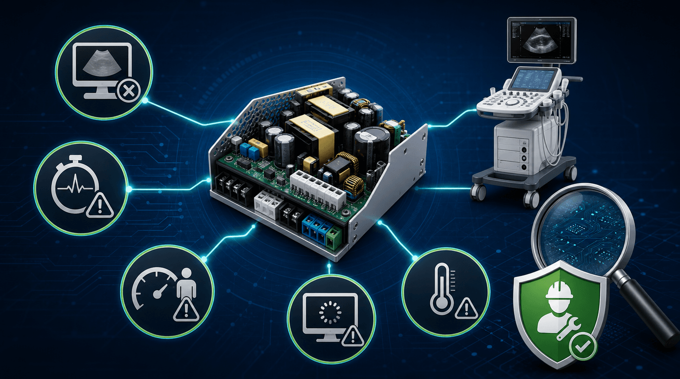
When a clinical ultrasound console fails to power on, shuts down mid-scan, or enters an infinite reboot loop, biomedical engineering teams and independent service organizations (ISOs) face immediate clinical downtime and diagnostic uncertainty. In multi-vendor fleet management, power subsystem failures are frequently misdiagnosed: a dead scanner is assumed to require a complete system replacement, or a failing DC power distribution board is mistaken for a main computer motherboard fault 8.
According to peer-reviewed failure mode, effects, and criticality analysis (FMECA) data covering 4,216 service events, the symptom cluster 'unable to power on' ranks as the second-most-frequent ultrasound failure mode, accounting for 11.69% of all documented equipment breakdowns 1. Resolving these failures efficiently requires a systematic, presentation-led decision path rather than trial-and-error board swapping.
This report provides a structured diagnostic framework for field engineers isolating power faults across major GE HealthCare (LOGIQ, Voluson, Vivid), Philips Healthcare (iU22, EPIQ), and Siemens Healthineers (Acuson S2000, Sequoia) platforms. Building upon our foundational GE ultrasound board symptom decision path, Philips board symptom decision path, and Siemens Acuson board decision path, this guide drills specifically into power-subsystem isolation, verified catalog part numbers, component-level rebuild economics, and 48-hour loaded acceptance testing.
What are the distinct no-power presentations on an ultrasound console, and which power-subsystem root cause does each point to?
Ultrasound console power subsystems consist of multiple staged units: primary AC-to-DC main power supplies (PSUs), auxiliary DC-to-DC power distribution boards (such as GE RSP, CPS, DPSS, and BEP power modules, Philips PRB power distribution boards, and Siemens PSD/AC units), cooling fan controllers, and motherboard init monitoring circuits. Rather than treating 'no power' as a single generic fault, field engineers must isolate the failure based on five distinct operational presentations observed during the boot sequence and scanning workflow.
1. Dead Console (No LEDs, No Fans, Silent Inlet): The console exhibits zero electrical activity when the primary power breaker or standby switch is engaged. No status LEDs illuminate on the rear interconnect panel or user interface, cooling fans remain stationary, and no audible relay click is heard. This presentation points directly to the primary AC power entry path: mains circuit breaker, AC inlet EMI line filter, primary AC fuses, or complete breakdown of the main AC/DC switching power supply primary stage (e.g., blown bridge rectifier or shorted switching MOSFETs).
2. Brief Power Activity / Shutdown Before OS Loading: Status LEDs or fans start briefly and the console returns to standby or dark state. A protection trip, overloaded downstream assembly, sequencing fault or failing supply are all candidates; the presentation alone does not identify which rail or component failed. Record the exact LED, log and timing evidence, then follow the model-specific service flow without bypassing protection circuits.
3. Reboot or Power-Off During Higher-Demand Scan Modes: The console boots and remains stable in a baseline mode but resets or shuts down when a repeatable scan mode increases system demand. Power delivery, cooling, the transmit path and software-controlled protection are competing hypotheses. Elevated capacitor ESR is one plausible mechanism, but it must be confirmed against the OEM rail limits and repeatable load evidence rather than inferred from the symptom alone.
4. Power Indicators Active but No Completed Boot: Fans or panel lights are active, but the display remains black or the system stalls at an OEM startup screen. This shifts the investigation toward power-good sequencing, host computer, storage, display path or initialization control; it does not by itself prove that the main PSU is healthy or that the motherboard is defective.
5. Cold-Start Intermittency vs Warm-Operation Shutdown: The console behaves differently at cold start or after a repeatable warm-up period. Capture elapsed time, ambient condition, fan status and workload. Cooling, connectors, power components and other temperature-sensitive assemblies remain candidates; controlled reproduction is required before assigning root cause 2.
| Presentation Signature | Primary Suspect Subsystem | Key Electrical / Physical Indicator | Safe First Isolation Step | Qualified Safety Hard Stop |
|---|---|---|---|---|
| Dead Console (No LEDs, No Fans) | Mains AC Inlet / EMI Filter / Main AC-DC PSU | No external power indication; inlet or protection evidence recorded | Verify the facility outlet and cord through approved external checks; document fuse/protection status without bypassing it | Do not open the AC path or make energized internal measurements unless qualified and following the OEM procedure. |
| Brief Power Activity then Shutdown | DC Power Distribution / Secondary Rail OCP | Protection LED, diagnostic code or repeatable downstream-load correlation | Record codes and follow the OEM isolation sequence; board disconnection is qualified-service work | Do not bypass DC circuit breakers or short OCP sense resistors. |
| Reboot / Shutdown During Color Doppler / 4D | HV Power Supply / Bulk Electrolytic Capacitors | A repeatable load-correlated reset plus out-of-limit evidence under the OEM test method | With power removed, qualified personnel may inspect for visible damage; electrical tests use OEM/component limits | Stored energy may remain after unplugging. Follow the OEM discharge and verification procedure before handling. |
| Fans & Lights Active, Display Black / Logo Hang | Host Computer Motherboard / BEP / SBC / SSD | Power-good and host-init evidence from the model-specific diagnostic flow | Capture codes and logs; follow the OEM host, storage and display isolation sequence | Do not swap host motherboards across un-matched system software revisions. |
| Repeatable Shutdown After Warm-Up | Cooling Fans / Power Supply Thermal Sensor / Heat Sink | Airflow obstruction, fan or thermal code, or temperature-correlated symptom | Record ambient condition and airflow evidence; service cooling hardware per the OEM procedure | Do not operate with safety covers or airflow panels removed except where an OEM service procedure explicitly requires it. |
How do I tell a main PSU failure from a DC-rail / power-distribution board fault or a no-boot motherboard / init fault?
Differentiating between primary AC/DC power supply failures, secondary power-distribution faults, and host-computer boot stalls is a critical troubleshooting step. Replacing a high-value assembly without an evidence gate wastes maintenance budget and prolongs downtime, regardless of the board's quoted price.
Understanding the Staged Power Architecture: Modern cart-based ultrasound systems utilize a multi-tier power architecture:
- Tier 1: Main AC/DC Power Supply Unit (PSU): Receives facility AC and creates the platform's primary DC outputs. Exact topology, voltages and protection behavior are model-specific.
- Tier 2: Power Distribution & Management Assembly (RSP, PSD, PRB, CPS): Sequences and distributes logic, analog and transmit-related power according to the console architecture. Acronyms and functions must be confirmed in the service documentation for the installed revision.
- Tier 3: Host Computer / Motherboard Power (BEP / SBC): Local converters and power-good logic support the host processor and related computing assemblies. A stalled boot can involve this tier even when some lights and fans are active.
The Failure Physics of Power Supplies: Electrolytic-capacitor ageing is one important wear-out mechanism in switching supplies. Heat, ripple current and time can increase ESR and reduce capacitance; whether that mechanism explains a particular console symptom requires component- and model-specific evidence:
- Equivalent Series Resistance (ESR) increases significantly—often reaching 2.8 times initial nominal rating before complete failure 2.
- Capacitance declines below 80% of nominal value, reducing total charge storage capacity.
- Ripple current causes localized self-heating (I²R losses), accelerating thermal degradation in a positive feedback loop until thermal runaway or open-circuit failure occurs.
As ESR rises and capacitance falls, output ripple and transient response can deteriorate. Whether that deterioration is sufficient to explain a reset or boot loop must be judged against the specific supply's component data and OEM limits under a controlled load test; generic millivolt thresholds should not be transferred between models 9.
For a deeper analysis of failure physics across ultrasound sub-assemblies, refer to our comprehensive study on ultrasound board-level failure patterns.
Which ultrasound power-supply and power-distribution board part numbers apply to GE, Philips and Siemens consoles, and why does revision matter?
When sourcing replacement power supplies or sending modules for component-level repair, capture the complete physical label, suffix, hardware revision, console configuration and software level. Different catalog identities must not be assumed interchangeable. Confirm fit and function through OEM documentation, a validated cross-reference or a qualified supplier's written compatibility record.
Rongtao Medical's public catalog dataset contains 525 board records, including 34 power-supply and power-distribution rows across 7 OEM brands 7. The table below is an identity cross-check drawn from those records. It does not establish live stock, failure frequency, revision interchangeability or compatibility with a specific console.
| OEM Brand & Console Model | Power Subsystem Assembly Name | Catalog Part Number / Identifier | Required Buyer Verification |
|---|---|---|---|
| GE LOGIQ E9 | Main AC/DC Power Supply | 5433408-21, 5205052-10, 5205052-3 | Match the complete label, suffix, connector set and installed LOGIQ E9 revision |
| GE LOGIQ E9 | BEP Small Power Board | 5393801, GA200876, 5393800-3 | Confirm which label is the orderable part number versus assembly identifier and verify the BEP generation |
| GE LOGIQ S8 | Main System Power Supply | 6003003 | Confirm installed label, hardware revision and connector layout |
| GE LOGIQ S7 / S8 | CPS (Console Power Supply) | 6626600, 5393431-3 | These records cover different catalog model groupings; do not treat the identifiers as interchangeable |
| GE LOGIQ F8 / F6 / T8 | System Power Board | 5440428-S, 5440428 | Verify the suffix and the exact F6/F8/T8 configuration |
| GE Voluson E8 / E10 | RSP3E Power Distribution Board | KTI303892-12, KTI303892-16 | Treat -12 and -16 as distinct identities until the installed BT/revision and OEM compatibility are documented |
| GE Voluson E6 | RSP2f Power Distribution Board | KTI302752-10, KTI302752 | Confirm whether the suffix is required for the installed system revision |
| GE Voluson S6 / S8 | CPS Power Module | 5393431-3, 5393431 | Verify the complete assembly label and S6/S8 configuration |
| GE Vivid E9 | System Main Power Supply | GA200730, 5166790-2 | Confirm which marking is the orderable number and match the installed Vivid revision |
| Philips iU22 / iE33 | Main AC/DC Power Supply Unit | 4535611151071, 453561279498 | The catalog records include different assembly types; verify the exact cart, label and function before ordering |
| Philips EPIQ 5 / 7 | System Power Board Assembly | 453561803892, 453561879752 | Confirm power-board versus power-supply identity and the installed EPIQ generation |
| Philips EPIQ 5 / 7 | PRB (Power & Relay Board) | 453561799432 | Cataloged for EPIQ A-Version; verify the full revision and connector set |
| Philips ClearVue 650 | Power Supply Assembly | 453561451365 | Confirm the physical label and ClearVue 650 configuration |
| Siemens Acuson S2000 | PSD (Power Supply Subsystem) | 07303659, 10439494 | These are separate PSD and AC-power catalog records; verify the required assembly and S2000 revision |
| Siemens Acuson Sequoia | Main Power Supply Unit | 10855235 | Identify the Sequoia generation and match the complete installed label |
| Siemens Acuson X700 | DC Power Distribution Module | 10790290 | Confirm the exact X700 configuration and hardware revision |
Why Board Revision Matching Matters: A shared base name or nearby suffix is not evidence of interchangeability. For example, the catalog contains separate RSP3E records for KTI303892-12 and KTI303892-16; it does not document that one can replace the other or specify their electrical differences. Record the physical label and system revision, then obtain an OEM or otherwise validated compatibility reference before ordering or swapping the assembly.
For guidance on evaluating board verification and acceptance standards, see our guide on ultrasound board part number verification and acceptance testing.
Is a power-supply board repairable at component level, or should I replace the whole unit?
When faced with a failed ultrasound power supply, healthcare engineering departments and ISOs must choose between three repair strategies: component-level board rebuild, advance exchange replacement, or purchasing a new OEM replacement assembly. In many cases, component-level power supply repair offers significant cost savings while maintaining full technical integrity.
Technical Feasibility of Power Supply Rebuilds: Some power-supply assemblies can be repaired at component level when the design, damage, documentation and required safety tests are within a qualified provider's capability. Others should be exchanged or replaced because of inaccessible construction, damaged insulation barriers, unavailable components or uncertain post-repair compliance. Feasibility must be decided after inspection, not from the symptom or board name alone.
Rongtao Medical's technical service archive documents extensive component-level power supply restoration capabilities:
- Case 13 (GE Voluson E8 Main PSU): The archive records a no-power fault, replacement of primary-rail capacitors and a control IC, rail verification under load, and a 48-hour live-chassis burn-in 6.
- Case 11 (GE Voluson E10 Main PSU): The archive records a power drop during boot, a PSU rail rebuild with capacitor refresh, and a 48-hour live-system burn-in.
- Case 12 (GE Voluson E8 RSX Power Management): The archive records a boot-time power-management error, replacement of a sequencing IC and rail monitor, output re-trimming, and verification of the power-good sequence.
| Repair Strategy | Cost vs New OEM Assembly | Turnaround Time | Technical & Financial Advantages | Best Suited Clinical Scenario |
|---|---|---|---|---|
| Component-Level Rebuild (Rongtao Service) | Materially below new OEM (billed as labor + components; final quote confirms) | 5 to 8 Business Days | Preserves the original assembly when repairable; require a repair record, 90-day warranty terms and the documented 48-hour service test | Non-emergency fleet maintenance; EOSL platforms with unavailable new parts; cost-sensitive ISO budgets |
| Advance Exchange (Tested Pre-owned) | Quote-dependent core-return exchange | Confirm live stock, dispatch, transit and core terms in the quote | Can reduce downtime when the exact compatible unit has passed incoming acceptance | High-volume hospital emergency rooms; critical imaging department single-console downtime |
| New OEM Replacement Assembly | Obtain the current OEM quote | Confirm with the OEM for the exact part and region | OEM provenance and warranty scope must be confirmed for the quoted assembly | Consoles under active OEM multi-year comprehensive service contracts |
To explore detailed financial and technical trade-offs across all board types, refer to our comprehensive analysis on ultrasound board repair vs replacement decision framework.
How do I accept a repaired or replacement power-supply board before returning the scanner to clinical use?
Returning an ultrasound console to clinical service after power-supply work requires documented identity, functional, load and electrical-safety acceptance. A brief unloaded power-on cannot demonstrate stability across the console's intended operating modes.
NASA Systems Engineering burn-in principles emphasize exercising the unit under representative loading rather than relying on idle operation 3. For medical equipment, the actual acceptance limits and methods must come from the OEM procedure, applicable safety standard and the repair provider's validated test plan.
Stage 1: Identity and Unpowered Inspection: Confirm assembly and revision identity, repair record, connector condition, workmanship, insulation barriers and visible damage. Any resistance or component-level measurements are performed by qualified personnel against model-specific reference values; a universal resistance cutoff is not appropriate across different rails and designs.
Stage 2: Controlled Bench Verification: Qualified personnel use the OEM-approved fixture or validated equivalent to check outputs, sequencing, protection behavior and ripple under controlled loads. Instrument category, isolation, probing method and pass limits must be defined for the specific assembly; generic voltage or ripple limits must not be substituted.
Stage 3: Target-Chassis Functional Load: After bench acceptance, verify the assembly in the correct console revision across startup, idle and representative scan workloads. Record repeatability, diagnostic logs and any protection event. Internal energized measurements remain restricted to qualified personnel following the OEM procedure.
Stage 4: Documented 48-Hour Service Soak: Rongtao's published service terms specify a 48-hour real-machine test. The acceptance record should identify the chassis, workload, start and finish time, interruptions and observed result; component temperatures are judged against the applicable design limits rather than a universal cutoff 6.
Electrical Safety Verification: Final release must include the electrical-safety tests applicable to the complete console, its protection class and the organization's procedure under IEC 60601-1 or adopted local requirements 4:
- Protective Earth: Record continuity or resistance using the applicable test current, points and limit for the equipment class and local procedure.
- Leakage Current: Record the required normal- and single-fault-condition measurements and compare them with the limits applicable to the complete system and test configuration.
- Essential Performance: Confirm startup, image formation, controls, alarms and shutdown behavior after reassembly; electrical-safety results alone do not establish clinical function.
For hospitals planning critical spare parts strategy for aging fleets, refer to our guide on which ultrasound spare parts to stock for an end-of-service fleet.
Frequently Asked Questions About Ultrasound Power Supply Diagnostics
Q1: My ultrasound is completely dead—no LEDs, no fans. Is it the power supply?
The external source, cord, inlet/protection path, main supply and downstream shorts are all candidates. Start with approved external power and cord checks, preserve any diagnostic evidence, and do not open or probe the internal AC path unless qualified and following the OEM service procedure. Confirm the failed assembly before ordering.
Q2: Why does my ultrasound shut down only during a higher-demand scan mode?
A repeatable load correlation can implicate power delivery or cooling, but it can also involve the transmit path, another downstream assembly or software-controlled protection. Capture the exact mode, probe, elapsed time and logs, reproduce under controlled conditions, and compare measured behavior with the OEM limits before assigning root cause.
Q3: Can an ultrasound power-supply board be repaired instead of replaced?
Some assemblies are repairable at component level; others are not appropriate candidates because of damage, construction, parts availability, documentation or safety-validation limits. A qualified provider should inspect the exact board, define the repair and acceptance evidence, and quote the options. Rongtao's documented cases show successful repairs on specific Voluson E8/E10 supplies, not a guarantee for every PSU.
Q4: What do BEP, PSD, RSP, CPS and PRB mean on a GE, Philips or Siemens label?
These are platform-specific assembly labels, not universal electrical definitions. Use the exact catalog entry and OEM service documentation for the installed model:
- BEP: GE catalog records use this label in the back-end-processor context; verify the full assembly name and LOGIQ generation.
- PSD: Siemens catalog records include S2000 PSD 07303659; distinguish it from AC Power 10439494.
- RSP: GE Voluson catalog records include RSP2f and RSP3E identifiers; suffixes remain revision-specific.
- CPS: GE catalog records use CPS across more than one console grouping; match the full model and part label.
- PRB: The catalog identifies Philips EPIQ A-Version PRB 453561799432 as a power-distribution board; verify the EPIQ revision.
Request a Power Supply Diagnosis or Replacement Quote
If your hospital biomedical engineering department, ISO, or refurbishing facility is managing a dead ultrasound console, boot loop, or power distribution failure, Rongtao Medical provides expert multi-brand board repair and advance exchange solutions.
To receive an immediate, actionable quote for component-level power supply repair or tested advance exchange parts, please prepare the following details before reaching out:
- Console Model & Software Version: OEM brand, exact model name (e.g. GE LOGIQ E9, GE Voluson E8, Philips iU22, Siemens Acuson S2000), system BT / release level, and year of manufacture.
- Power Board Part Number & Revision: Exact OEM part number printed on the physical board silkscreen barcode label (e.g., GE 5433408-21, GE RSP3E KTI303892-16, Philips 4535611151071, Siemens 07303659). Clear photos of BOTH front and back sides of the board are highly recommended.
- Exact Power Fault Symptom: Detailed description of presentation (completely dead / brief power pulse then trip / reboot during Color Doppler / fans running but no boot / thermal shutdown after X minutes).
- Fault Occurrence Profile: Cold boot vs warm operation, intermittent vs 100% reproducible, specific probe or scan mode involved.
- Service Requirement & Target Destination: Component repair service vs advance exchange core swap, required quantity, and delivery country/city.
Explore our live parts catalog or GE ultrasound service pages, or submit your technical details directly via our Rongtao Medical contact and quote request form. Our engineering team typically responds within 24 hours with diagnostic guidance, repair feasibility, turnaround timelines (standard 5–8 business days), and 90-day warranty coverage terms.