
What Does the Front-End Beamformer Board Do, and Which OEM Labels Point to It Across GE, Philips, Siemens, Canon, Hitachi/Aloka, and Mindray?
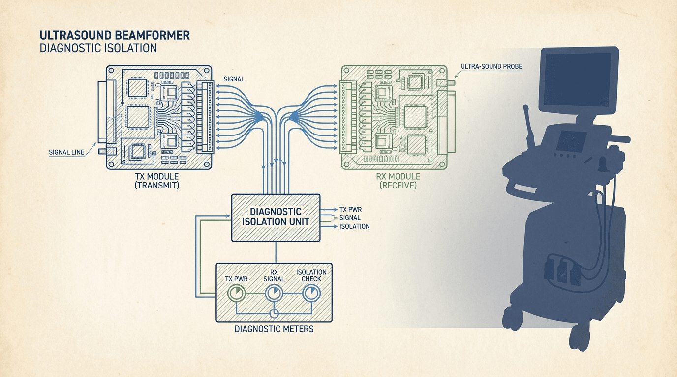
In diagnostic ultrasound architecture, the electronic processing pipeline is divided into three distinct operational stages: echo transmission, echo acquisition, and back-end display processing 1. The first two stages—transmission and acquisition—comprise the system's front-end. High-voltage pulser circuits on the transmit side send timed electrical pulses to piezoelectric crystal elements within the transducer, while low-noise amplifiers (LNAs), variable gain amplifiers (VGAs), and high-speed analog-to-digital converters (ADCs) on the receive side capture and digitize tiny returning acoustic echoes. The beamformer board coordinates these micro-delay pulse trains across 64, 128, 192, or 256 physical channels to synthesize coherent acoustic scan lines.
Because front-end electronics dissipate significant thermal energy, manage high-voltage switching pulses (often ranging from ±50V to ±100V DC), and interface directly with external patient-contacting probes, they experience higher electrical stress than static back-end scan converters 1. When an acoustic image exhibits vertical black bands, total loss of echo signal, severe shadow lines, or persistent digital pattern noise, field service personnel often suspect a front-end hardware failure. However, navigating multi-brand service manuals is complicated by manufacturer-specific nomenclature.
Rongtao Medical's verified multi-brand ultrasound board catalog encompasses 254 distinct circuit board SKUs across 10 major OEM brands. Within this catalog, more than two dozen specialized SKUs represent front-end beamformer, transmit/receive (T/R) switch, and signal acquisition modules 10. Identifying the exact OEM designation on board labels is the first step toward sourcing a tested replacement or requesting board-level repair.
| OEM Manufacturer | Target System Families | Front-End / Beamformer Board Designation | Primary Electronic Function |
|---|---|---|---|
| GE HealthCare | Voluson E8 / E10 / P8 / S6, LOGIQ E9 / E10 / E11, Vivid E9 / E95 | RFM, RFI, RSX, DRX, GTX, GRX, GBF, ETX, DTRX, DBM64 | Radio Frequency Module (RFM), Digital Receiver (DRX), Transmitter (GTX), 64-Channel Beamformer (DBM64) |
| Siemens Healthineers | Acuson S2000 / S3000, Antares, G50 / G60 / X300 | TXBF, RXBF, BWPR, FERX, Acquisition Board | Transmit Beamformer (TXBF), Receive Beamformer (RXBF), Front-End Receive (FERX), Back-End Processor (BWPR) |
| Canon / Toshiba | Aplio 300 / 400 / 500, Aplio i700 / i800, Xario 100 / 200, SSA-550A | FERX, TXBF, RXBF, Channel Board, Front-End Assembly | Front-End Receiver Board (FERX), Multi-Channel Transmit/Receive Matrix, Analog Front-End |
| Hitachi / Aloka | ProSound Alpha 6 / Alpha 7, Arietta 60 / 70, F75 | DBF, DBF-B, Channel Board, TXRX Board, RXRX Board | Digital Beamformer (DBF), Channel Transmit/Receive Board, High-Density Acoustic Acquisition |
| Philips Healthcare | EPIQ 5 / 7, Affiniti 50 / 70, HD11 XE, HD15, HDI 4000 | FE Channel Board, BF Board, Front-End Acquisition | Front-End Acquisition Board, Multi-Channel Digital Beamformer Array |
| Mindray Medical | Resona 7 / 8, DC-70 / DC-80, M9, TE7 | TR Channel Board, Transmit/Receive Board, Main Front-End | Transmit/Receive Channel Processing, Transducer Interface High-Voltage Matrix |
Source: Rongtao Medical Verified Parts Catalog & Inventory Ground Truth (August 2026)
When referencing front-end assemblies, biomedical engineers must distinguish between dedicated single-brand symptom paths and universal board-role isolation. Readers managing specific platforms should consult our dedicated brand guides, such as the GE Voluson, LOGIQ and Vivid front-end board symptom decision path, the Siemens Acuson receive and transmit beamformer symptom path, or the Canon/Toshiba Aplio front-end and channel board path, which provide platform-specific board part numbers and jumper settings.
No Image or Channel Dropout: How Do You Separate a Board Fault from a Probe or Cable Fault?
The single most common diagnostic error in ultrasound service is misdiagnosing a probe or cable defect as a front-end board failure—or vice versa. An acoustic image artifact such as a vertical dark stripe in B-mode imaging can be produced by several completely different fault domains 4 5:
- Transducer Acoustic Array: Cracked, debonded, or oxidized piezoelectric elements, acoustic lens delamination, or fluid ingress into the crystal housing.
- Transducer Cable Harness: Broken micro-coaxial wires inside the flexible cable bundle caused by severe bending, clamping, or strain-relief breakdown.
- Probe Connector Pin Matrix: Bent, retracted, oxidized, or contaminated pin contacts inside the probe connector housing.
- Console Connector Receptacle: Damaged pins, debris, or broken locking cams on the system's probe selector board / multiplexer port.
- System Front-End Board: Blown high-voltage transmit pulsers, failed pre-amplifier ICs, open T/R switches, or dead ADC channels on the beamformer board.
Published surveys of medical ultrasound transducers in clinical active duty report that approximately 20% to 30% of probes suffer from degraded performance, acoustic dropouts, or dead element clusters 3 4. On linear and convex arrays, a group of dead elements appears as a sharp vertical shadow band. On phased-array cardiac probes, however, acoustic signals from individual elements are synthesized across the entire scan sector; consequently, element dropouts degrade overall image contrast, SNR, and lateral resolution rather than producing a single clean black line 5.
To establish conclusively whether the defect resides inside the transducer or inside the system console front-end, field technicians must perform a systematic four-step swap protocol before ordering replacement parts 2 3:
- Step 1 (Port Isolation on Same Console): Disconnect the suspect probe from Port 1 and connect it to Port 2 or Port 3 on the same ultrasound machine. Inspect the live image. If the vertical dropout or artifact disappears or changes character, suspect a damaged port connector pin or multiplexer switch on the system probe select board.
- Step 2 (Cross-Console Probe Test): Move the suspect probe to a secondary, known-good ultrasound console of the same model series. If the exact same dropout pattern appears on the second console screen, the fault is 100% isolated to the probe acoustic array, cable harness, or probe connector. Refer to our detailed guide on ultrasound probe repair vs replace.
- Step 3 (Known-Good Probe Test on Suspect Console): Connect a known-good probe of identical model (or similar array class) to the original suspect port on the primary system. If the image dropout or channel noise remains present in the exact same physical screen sector across multiple probes, the fault is isolated to the console front-end / beamformer electronics.
- Step 4 (Acoustic Element Verification / IPEM Paperclip Test): Under in-air reverberation mode, move a metal paperclip lightly across the acoustic lens faceplate 3. Observe the corresponding M-mode or B-mode reverberation lines. Missing reverberation lines that persist across different probes confirm dead system receive channels.
| Suspect Probe on Alternate Port | Suspect Probe on 2nd System Console | Known-Good Probe on 1st Console | Isolated Fault Location | Recommended Action Route |
|---|---|---|---|---|
| Artifact Persists | Artifact Persists | Normal Image (No Artifact) | Transducer Assembly (Array / Cable / Plug) | Route transducer to probe repair (lens/cable) or probe replacement 2 |
| Artifact Clears | Normal Image | Artifact Persists on Port 1 Only | Console Probe Port / Multiplexer Board | Inspect port pins; clean contacts; replace probe selector board |
| Artifact Persists | Normal Image | Artifact Persists Across All Ports | Front-End / Beamformer Board Electronics | Route board to component repair or tested replacement 10 |
| Intermittent / Noise | Intermittent / Noise | Intermittent / Noise | System Grounding / High-Voltage PSU Rail | Check wall outlet ground, AC line filter, and system power supply |
Source: Avante Health Solutions Troubleshooting Protocol & IPEM Multicentre Survey Synthesis
When Symptoms Persist Across Probes: Which Front-End Board Is Likely Defective and What Evidence Should You Collect?
Once the swap protocol establishes that an image artifact or channel defect persists across multiple known-good probes, the engineer must isolate which specific board within the front-end card cage is responsible. Ultrasound front-end card cages generally house transmit boards (high-voltage pulser arrays), receive/acquisition boards (pre-amps and ADCs), and digital beamforming/summation processors.
By evaluating the precise visual appearance and thermal behavior of the failure, technicians can narrow down the suspect circuit module before opening the console chassis:
- Transmit Pulser (TX) Board Failure: Manifests as a total acoustic blackout across all probes, an inability to fire high-voltage Doppler pulses, or a dark vertical wedge that remains fixed regardless of probe frequency. A shorted high-voltage pulser MOSFET often trips the system power supply or generates an immediate high-voltage fault code.
- Receive Acquisition (RX / FERX) Board Failure: Manifests as severe background snow, fixed vertical pattern lines, missing weak-echo signals, or loss of gain control. Individual channel pre-amplifier IC failures create faint vertical lines, whereas an analog-to-digital converter (ADC) clock failure drops an entire block of 16 or 32 channels.
- Digital Beamformer (DBF / RFM) Module Failure: Manifests as phase distortion, loss of lateral spatial resolution, image tearing, or complete failure of acoustic line summation. In GE Voluson systems, the RFM (Radio Frequency Module) handles complex digital beamforming; a channel mapping error inside the RFM creates image artifacts across all 3D/4D volume probes.
- Thermal-Dependent Channel Failure: The system boots normally and produces pristine images for 10 to 20 minutes, after which vertical dropout or image freezing occurs. Thermal expansion causes cracked solder joints under BGA channel chips to open, or thermal protection circuits on power management ICs to shut down transmit rails.
Rongtao Medical's technical repair archive includes documented field cases demonstrating these exact fault signatures 10. For example, a GE Voluson E10 presenting persistent acoustic image anomalies across all attached probes was bench-isolated to the RFM beamformer module; replacing failing front-end ICs and recalibrating the channel map fully restored system performance. In another case involving a GE Voluson P8 DBM64 (64-channel digital beamformer), the fault was strictly thermal-dependent; thermal cycling on the test bench reproduced the open solder connections, which were resolved by BGA reflow and thermal interface renewal.
Case Study Insight: When a GE Voluson P8 presented an image dropout that only appeared after 20 minutes of clinical operation, routine cold diagnostic tests showed zero errors. Only by mounting the DBM64 beamformer on a live chassis in a temperature-controlled test chamber was the thermal expansion failure captured. Reflowing the suspect channel ICs and refreshing the thermal pads eliminated the fault without requiring an expensive new board assembly.— Rongtao Medical Technical Repair Log (Case Ref: DBM64-P8-THERMAL)
Before requesting a replacement board or submitting a repair RFQ, biomedical engineers should collect a complete technical evidence package. Providing thorough diagnostic evidence ensures rapid quote turnaround and guarantees part compatibility.
| Required Information Field | Specific Data / Image Required | Why This Information Is Critical |
|---|---|---|
| System Console Identification | Full OEM brand, exact model name, software version / revision letter | Front-end boards often have hardware rev dependencies tied to software release |
| Board Part Number & Labels | High-resolution photos of front and back board labels, revision stickers, bar codes | Identifies exact OEM FRU number (for example GE 5728959, 5301160-6) and circuit rev |
| Visual Symptom Photographs | Screen capture or photo of B-mode / Color Doppler artifact with probe model visible | Helps repair engineers determine TX vs RX vs beamformer summation failure |
| Probe Swap Results | Documented outcomes of 4-step swap protocol (models tested, ports used) | Proves fault resides in console front-end rather than transducer cable |
| System Diagnostic Logs | Exported error log text file or photos of service desktop fault codes | Provides exact register fault addresses for bench troubleshooting |
| Physical Inspection Notes | Note any visible burnt ICs, blown fuses, liquid ingress, or burnt smells | Prevents damaging test bench chassis when board is plugged in for evaluation |
Source: Rongtao Medical Service Handoff Protocol
What Can System Error Logs Tell You About a Beamformer Fault (and Where Do They Mislead)?
Modern ultrasound systems feature sophisticated internal self-diagnostics and error logging tools (such as GE's Service Desktop / Alt+D logs, Siemens' Syngo Event Viewer, or Philips' TechAdmin diagnostics). When a hardware fault occurs, system software writes hex code entries, register dump files, and textual error descriptions to local log files 1.
However, biomedical engineers must exercise caution when reading error logs. While an error log is valuable for indicating general system distress, error log entries are not always accurate indicators of root-cause hardware failures 1. Acoustic test laboratories and experienced field engineers note several common error log pitfalls:
- Cascading Bus Downstream Errors: If a 15V power rail on the main power supply (PSU) drops out, the front-end ADCs lose power. The system log will register a 'Beamformer Communication Timeout' or 'FE FPGA Reset Failed'—leading an unsuspecting technician to replace the beamformer board when the actual culprit is the power supply.
- Transducer Short-Circuit Artifacts: A pinched probe cable that shorts a high-voltage transmit line to ground can cause the transmit board protection circuit to trip. The error log will report 'TX High Voltage Rail Overcurrent Failure', misdirecting service focus toward system electronics.
- Missing Clock Signal Traps: A master clock synthesizer failure on the back-end host motherboard will cause all digital acquisition ADCs on the front-end board to report synchronization errors simultaneously.
To avoid replacing healthy circuit boards, always triangulate error log findings against empirical physical testing. Run the OEM service manual's built-in functional diagnostics (e.g., GE's Probe Diagnostic Test / FE Self-Test, Siemens SysTest) alongside the physical probe swap protocol. For further insights into complex failure physics, review our analysis of documented ultrasound board failure patterns.
Should You Repair the Board, Buy a Tested Replacement, or Request an Advance Exchange?
When a front-end beamformer board is confirmed defective, healthcare facility managers, ISO service directors, and equipment distributors face a commercial decision: should they send the board for component-level repair, purchase an outright tested replacement, or request an advance exchange?
Understanding the commercial trade-offs between these options allows service teams to minimize system downtime while optimizing maintenance budgets. For a broader economic framework, see our report on ultrasound board repair vs replacement decision.
| Resolution Route | Typical Turnaround | Cost vs OEM New Board | Primary Advantage | Ideal Clinical / Service Scenario |
|---|---|---|---|---|
| Component-Level Board Repair | 5 to 8 business days 10 | Lowest | Lowest total repair cost; preserves original OEM board subassembly | Non-urgent repairs, backup consoles, cost-sensitive ISO contracts |
| Outright Tested Replacement | Immediate dispatch (1 to 3 days) | Highest | Zero core return required; builds internal spare parts buffer | High-volume hospitals needing permanent local emergency stock |
| Advance Exchange | Immediate dispatch (1 to 2 days) | Mid-range | Fastest clinical restoration with core return credit | Critical emergency room / ICU console down situations |
Source: Rongtao Medical Service Operations & Quality Management System
In component-level board repair, skilled micro-soldering technicians replace defective pre-amp ICs, high-voltage switching FETs, damaged line filters, and degraded capacitors on the original PCB. Many confirmed front-end faults are localized to a small number of failed components, so a verified component-level repair frequently avoids the cost and lead time of a complete replacement board — as illustrated by documented cases such as the Voluson E10 RFM front-end IC replacement and the Voluson P8 DBM64 solder-joint reflow 10.
However, repair quality depends entirely on post-repair testing rigor. A repaired beamformer board cannot be validated using a multimeter on a static workbench; it must be installed into an actual matching ultrasound console and operated under full thermal and acoustic load. Rongtao Medical enforces a strict quality standard: every repaired board undergoes 48-hour continuous real-machine testing inside a live ultrasound chassis before sign-off, backed by ISO 13485:2016 certified processes and a standard 90-day warranty 10. Review our complete 48-hour real-machine test evidence for repaired boards protocol for quality verification steps.
What Are the Essential Safety Hard-Stops Before Re-Powering or Escalating Circuit Board Servicing?
Working with high-voltage medical electronics entails strict safety precautions. Transmit pulser boards on modern ultrasound consoles drive high-voltage switching pulses commonly on the order of ±100V DC, and high-frequency switching circuits store electrical energy in large capacitor banks even after AC power is removed.
Biomedical technicians must observe immediate hard stops and refrain from re-powering an ultrasound console under the following conditions 6:
- Visible Burning or Charred Components: If an internal inspection reveals burnt IC packages, blackened PCB substrate, or melted connector housings, applying AC power can cause cascading short circuits into adjacent back-end host boards.
- Pungent Thermal Smell or Smoke: Turn off the main breaker immediately. Smoke indicates active component breakdown or thermal runaway in transmit power MOSFETs.
- Liquid Contamination on Probe Ports: Conductive ultrasound gel or cleaning fluid spilled inside probe connector ports creates direct high-voltage shorts across pin rows.
- Repeated Main Circuit Breaker Tripping: If powering on the system instantly trips the facility circuit breaker or system main breaker, a shorted primary power supply or transmit rail exists.
From a regulatory compliance standpoint, independent service organizations must operate within clear legal boundaries. The U.S. FDA's 2024 Final Guidance on Remanufacturing of Medical Devices establishes a clear distinction between servicing and remanufacturing 7. Servicing—defined as restoring a device to its original performance specifications without changing its intended use or safety profile—includes component-level circuit board repair, replacing worn connectors, and updating solder joints with OEM-equivalent parts. Conversely, altering circuit board layout, replacing custom FPGAs with unapproved code, or modifying high-voltage transmit parameters constitutes device remanufacturing, which triggers complex regulatory filing obligations. Rongtao Medical's repair procedures adhere strictly to servicing boundaries.
Where Does Rongtao Medical Fit in Multi-Brand Beamformer Repairs — and Where Do We Not?
To maintain transparent commercial relationships, we clearly define our technical capabilities and operational boundaries for healthcare providers, ISOs, and distributors.
Where Rongtao Medical Fits:
- Multi-Brand Board Repair Capacity: We provide component-level repair for front-end beamformer, transmit, receive, power supply, and control boards across GE, Philips, Siemens, Canon/Toshiba, Hitachi/Aloka, and Mindray ultrasound systems 10.
- Verifiable Tested Inventory: We maintain a photo-backed inventory of 254 distinct board SKUs, offering tested outright replacement and advance exchange options for critical system downtime.
- 48-Hour Real-Machine Verification: Every repaired or tested board is subjected to 48 hours of continuous operation inside an actual live ultrasound chassis under ISO 13485:2016 quality management system controls.
- Standard Service Terms: Standard 5-to-8 business-day repair turnaround with a typical 90-day warranty (extended warranty terms available upon request).
Where Rongtao Medical Does Not Fit:
- On-Site Clinical Field Service: We operate as a dedicated technical repair lab and parts supplier; we do not dispatch field service engineers to hospital clinical suites for on-site troubleshooting.
- Unauthorized Remanufacturing or Board Modification: We do not alter OEM circuit designs, reprogram security FPGAs, or perform unvalidated hardware hacks.
- OEM Authorization Claims: Rongtao Medical is an independent service provider and parts specialist. OEM brand names (GE, Philips, Siemens, Canon, Hitachi, Mindray) are used exclusively to state hardware compatibility.
Frequently Asked Questions: Beamformer & Front-End Board Fault Isolation
Q1: Can a failed or shorted ultrasound probe damage the front-end / beamformer board?
Yes. If a transducer cable harness suffers severe physical damage or conductive fluid ingress, high-voltage transmit pulses (up to ±100V DC) can short directly to low-voltage receive channels or signal ground lines. This high-voltage spike can blow protection diodes, burn T/R switches, and destroy sensitive pre-amplifier ICs on the front-end board. Always inspect probe pin contacts and cable integrity before connecting a damaged probe to a newly repaired console board.
Q2: My image dropout clears when I move the probe to another port — is it the board or the connector/port?
If an image dropout occurs on Port 1 but completely disappears when the exact same probe is connected to Port 2 or Port 3, the front-end beamformer channel electronics are fully functional. The fault resides in the Port 1 mechanical receptacle (bent/retracted contact pins, debris) or on the internal probe select / multiplexer board that switches channel lines between ports. Inspect the port receptacle visually and clean contacts with approved electronic contact cleaner before ordering parts.
Q3: What photos and information do I send to get a beamformer / front-end board repair quote?
To obtain an immediate, accurate quote, provide: (1) The exact ultrasound console make, model, and software revision letter; (2) Clear photos of both sides of the board, focusing on OEM part number stickers, bar codes, and PCB revision numbers; (3) Screen captures of the image defect; (4) The outcome of your 4-step probe swap test; and (5) Your destination country and urgency level. You can submit these details directly via our front-end, beamformer, RF and channel boards repair guide hub or through our technical quote request form.
Q4: Is vertical dropout always a dead probe element, or can it be a receive (RX) channel fault?
While a single dead crystal in a linear array causes a narrow vertical dropout line, a dead receive (RX) channel on the beamformer board can produce an identical vertical black stripe. The distinguishing test is probe swapping: if the dropout line remains in the exact same physical position on the screen when testing three different probes of different frequencies, it is a receive channel fault on the board. If the dropout line moves or disappears with different probes, it is an acoustic element or cable failure within the original transducer. For probe repair routing, explore our specialized probe repair services.