
What Does the Back-End Image-Processing / Acquisition Board Do, and Which OEM Labels Point to It Across GE, Philips, Siemens, Canon, Samsung, Mindray, and Hitachi/Aloka?
In diagnostic ultrasound system architecture, the electronic signal chain is divided into three functional stages: echo pulse transmission, raw channel acquisition, and back-end image processing / scan conversion 1. While the analog front-end beamformer coordinates high-voltage transmit pulses and digitizes multi-channel acoustic reflections (as detailed in our guide to front-end beamformer board failures), the back-end image-processing board receives synchronized digital radio-frequency (RF) or I/Q signal streams and transforms them into clinical B-mode grayscale images, Color Flow Doppler velocity maps, and Spectral Doppler audio/waveforms.
The back-end subsystem handles complex mathematical and graphics processing algorithms, including digital filtering, dynamic range compression, speckle reduction, spatial compounding, scan conversion (converting polar acoustic coordinates into raster video frames), 3D/4D multiplanar rendering, and video signal output generation 1. Because back-end boards combine high-speed Digital Signal Processors (DSPs), Field Programmable Gate Arrays (FPGAs), graphics processing units (GPUs), and dedicated system CPU modules, they operate under heavy processing loads and continuous thermal stress. Over time, thermal cycling, solder joint degradation, and power filtering component aging lead to system instability, image artifacts, and processing freezes.
Biomedical engineering teams and field service technicians navigating multi-vendor diagnostic fleets often struggle to identify the correct back-end board due to non-standard manufacturer nomenclature. In Rongtao Medical's verified multi-brand ultrasound board catalog—encompassing 254 circuit board SKUs across 10 major OEM brands—back-end processing modules are categorized by specific OEM assembly part numbers and functional designations 8. As analyzed in our cross-board field guide on board-level failure patterns, identifying the exact OEM board label is mandatory before sourcing replacement parts or initiating component-level rework.
| OEM Manufacturer | Target System Families | Back-End / Image-Processing Board Designation | Primary Electronic Function & Circuitry |
|---|---|---|---|
| GE HealthCare | Voluson E8 / E10 / P8, LOGIQ E9 / E10, Vivid E9 / E95 | Motherboard, System Control Board, Hardware-Init / Config Card, RSX Module, Main PC Box | Host processing, scan conversion, PCI express bus routing, graphics rendering, and system boot sequencing |
| Philips Healthcare | EPIQ 5 / 7, Affiniti 50 / 70, HD15, CX50 | Acquisition Processor (AP), Host CPU Board, Display Processing Unit (DPU), Video Interface Card | Channel data reconstruction, Doppler FFT spectral estimation, image frame buffering, and video pipeline encoding |
| Siemens Healthineers | Acuson S2000 / S3000, Acuson Sequoia, Acuson Juniper | Image Processor Board (IPB), Signal Reconstruction Board, Back-End Controller (BEC) | B-mode grayscale filtering, spatial compounding calculations, color flow velocity mapping, and DICOM video export |
| Canon / Toshiba | Aplio 300 / 400 / 500, Aplio i800 / i900, Xario 100 / 200 | Main Board, Signal Processing Board, Scan Converter Unit, Video Output Module | Polar-to-raster coordinate conversion, speckle suppression processing, multi-frequency synthesis, and display timing |
| Samsung Medison | HS50 / HS60 / HS70, WS80A, Hera W10, Accuvix A30 | PC Main Board, PCI Interface Board, DVI/Video Processing Board, Control CPU Card | Windows OS host control, ultrasound processing engine interface, video DAC encoding, and peripheral bus management |
| Mindray Medical | Resona 6 / 7 / 8, DC-70 / 80 / 90, M7 / M9 | Motherboard / Main Processing Board (e.g., DC-70 Motherboard 051-001451), Video Processing Card | Main processing bus, scan and image-processing engine interface, touchscreen video output, and system power management |
| Hitachi / Aloka | ProSound F75 / Alpha 6 / 7, Arietta 60 / 70 / 80 | Digital Image Processing (DIP) Board, Scan Converter Board, System Processor Card | Broadband harmonics processing, Doppler audio synthesis, real-time video scaling, and system master clock distribution |
Source: Rongtao Medical Verified Parts Catalog & Technical Service Ground Truth (August 2026)
Which Symptoms Point to a Back-End Board Fault Rather Than a Probe Defect?
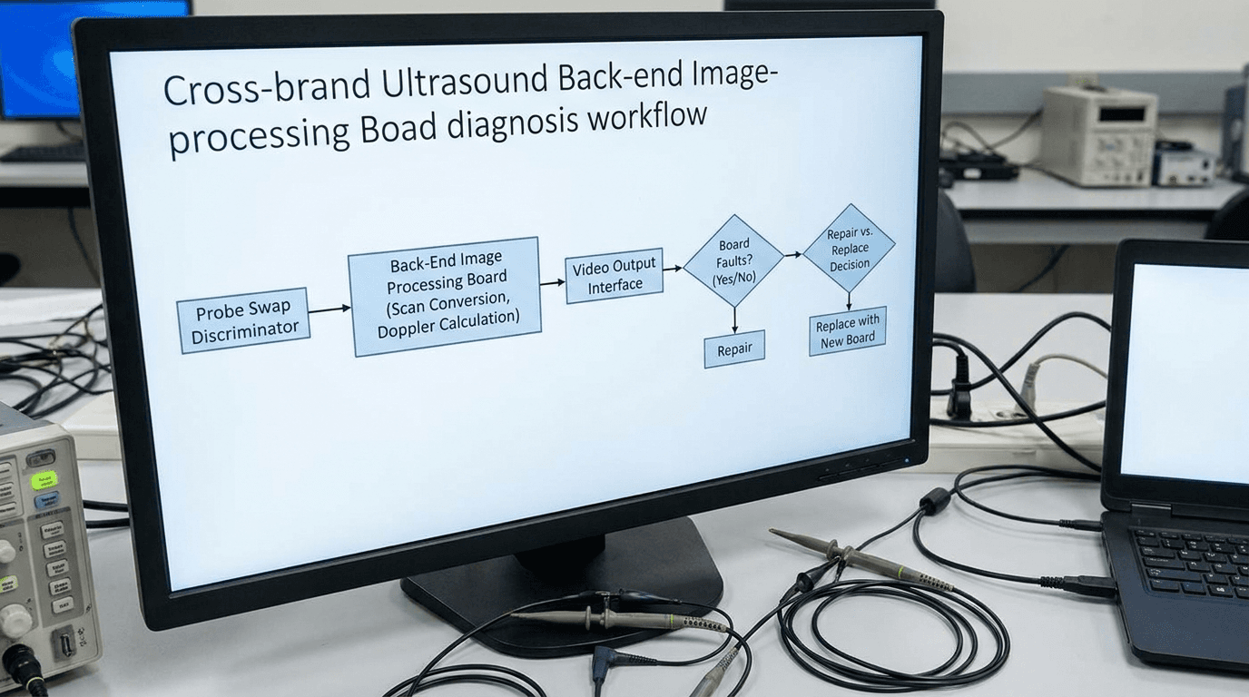
When an ultrasound scanner exhibits severe image quality defects, clinical users frequently assume that the connected transducer has failed. Acoustic array delamination, dead piezoelectric elements, or broken coaxial wiring inside the probe cable can indeed cause vertical dropouts and signal attenuation 3. However, replacing an expensive probe when the underlying root cause is a failing back-end scan converter results in wasted expenditure and prolonged equipment downtime. Biomedical engineers must execute a disciplined 4-step swap isolation protocol to determine whether the fault resides in the probe, the front-end beamformer, or the back-end image processor.
- Step 1: Document Artifact Behavior Across Modes — Note whether the anomaly affects B-mode grayscale, Color Flow Doppler, Spectral Doppler, or 3D volume modes, and check if on-screen menus and patient banners remain intact 2.
- Step 2: Swap Transducer to Secondary Console Port — Move the suspect probe to a different active port (e.g., from Port 1 to Port 3) on the same console. If the artifact disappears or changes pattern, suspect a damaged port connector or front-end multiplexer board rather than a back-end board.
- Step 3: Test Suspect Probe on a Secondary Matching Console — Connect the suspect transducer to a known-good console of identical make and model. If the image artifact follows the transducer, the failure is a confirmed probe defect (element dropout, lens damage, or cable fatigue) 3.
- Step 4: Test Original Console Port with a Known-Good Probe — Connect a known-good probe of identical or similar frequency to the original port. If the exact same image artifact, geometry distortion, or mode freeze persists across multiple probes, the fault is isolated to the console electronics (front-end beamformer or back-end image processor) 1 2.
To separate front-end beamformer channel failures from back-end image-processing board failures, analyze how the artifact behaves across different imaging applications and probe geometries. Front-end beamformer failures manifest as vertical black bands or missing channel lines that vary in position when switching between linear, convex, and phased array probes. In contrast, back-end image-processing board failures produce global scan-conversion errors, persistent horizontal banding, Doppler calculation lockups, or system freezes that occur across all connected probes regardless of frequency or element count 1.
| Diagnostic Parameter | Probe / Transducer Defect | Front-End Beamformer Board | Back-End Image-Processing Board | Display Monitor & Video Cable |
|---|---|---|---|---|
| Behavior During Probe Swap | Artifact moves with the probe when connected to another console | Artifact stays on console; changes pattern between probe geometries | Artifact stays on console; identical across all probes and ports | Artifact stays on console; present even with no probe connected |
| On-Screen UI & Menu Quality | Menus, patient text, and TGC bars are completely normal | Menus, patient text, and TGC bars are completely normal | Menus and text usually normal; image area corrupted or frozen | Menus, patient text, and acoustic image are ALL distorted/corrupted |
| Primary Clinical Symptoms | Vertical acoustic dropouts, weak penetration, lens shadow lines | Multi-channel black bands, noise spikes, missing elevation lines | Geometry tearing, Doppler FFT freezes, B-mode speckle artifacts | Screen flickering, color tint shift, total loss of backlight |
| External Video Output Test | External monitor shows identical probe dropout lines | External monitor shows identical beamformer channel lines | External monitor shows identical image processing corruption | External monitor displays crisp image; internal monitor distorted |
| Root Cause Mechanism | Piezoelement crack, acoustic lens wear, cable pin damage | Failed pulser IC, LNA burnout, T/R switch short, ADC failure | DSP memory error, FPGA timing breakdown, GPU thermal degradation | LCD panel backlight breakdown, LVDS cable damage, DAC failure |
Source: Rongtao Medical Technical Service & Diagnostic Isolation Framework (2026)
How Do I Separate a Scan-Conversion or Video-Output Board Fault from the Display Monitor?
A common point of confusion during field troubleshooting is distinguishing between a failure in the back-end video generation pipeline (scan-conversion board, graphics GPU, or video DAC) and a failure of the physical display monitor assembly (LCD panel, backlight inverter, or internal video ribbon cable). As outlined in our troubleshooting guide for ultrasound control panel and display failures, mistaking a video board fault for a broken LCD screen leads to unnecessary monitor replacements.
The back-end video pipeline functions in two distinct rendering passes: acoustic image scan conversion and On-Screen Display (OSD) menu composition 1. Acoustic scan conversion translates acoustic vector samples into a rectangular or sector video frame buffer. Next, the graphics processor overlays patient identification text, Gain/TGC slider indicators, acoustic measurement callouts, and system menu banners over the frame buffer before outputting a unified digital video signal (DVI, HDMI, or DisplayPort) to the display assembly.
Field service personnel can execute two decisive tests to isolate the failure:
- The Menu & Overlay Verification Test: Freeze the live image and open the system utility or setup menu. Observe whether text characters, measurement cursors, and menu dialog boxes are crisp, sharp, and correctly colored. If system menus are perfectly legible while the underlying ultrasound image area exhibits pixelation, geometric distortion, or static noise, the physical display monitor and video transmission cable are operating correctly. The fault is isolated to the scan conversion DSP or frame buffer memory on the back-end image-processing board 1.
- The Dual-Monitor External Video Test: Connect an external LCD monitor to the console's secondary DVI, HDMI, or VGA output port located on the rear connector panel. Compare the image on the external monitor with the internal main display. If the external monitor exhibits the exact same video artifacts, color corruption, or image tearing as the main display, the failure originates upstream in the back-end video processing board or GPU. If the external monitor displays a perfect, uncorrupted image while the internal main display shows distortion, the fault is isolated to the internal LVDS/eDP display cable or the console's LCD monitor assembly.
Can a Software, Configuration or Initialization Fault Mimic a Back-End Board Failure?
Yes. Diagnostic ultrasound consoles rely on complex operating system environments (typically custom Windows Embedded, VxWorks, or Linux builds) coupled with proprietary hardware abstraction drivers. When a system experiences operating system file corruption, corrupted user preset databases, or CMOS memory loss, it can exhibit symptoms that closely mimic a hardware back-end board failure, such as boot freezes, missing Doppler modes, or processing lockups 8.
In Rongtao Medical's technical repair archive of 16 multi-brand board cases, 5 cases involved back-end and system-control layer failures. Notably, Case-08 (GE Voluson E8 hardware-init/configuration failure) presented as an auto-reboot loop in which the console reported a hardware-initialization and configuration failure during boot. Field technicians initially suspected a defective motherboard. However, detailed board-level bench testing traced the fault to degraded front-end voltage rails feeding the hardware-init and configuration logic, together with a corrupted configuration EEPROM, rather than the motherboard itself 8. Rebuilding the affected voltage rails and reflashing the configuration EEPROM restored single-pass boot, confirmed by a 48-hour live-system soak — without requiring a costly motherboard replacement.
Before condemning a back-end board, service teams should execute the following software and configuration verification protocol:
- Cold Power Cycle with AC Mains Isolation: Turn off the system breaker, disconnect AC mains power for 5 minutes to dissipate standby voltage rails, and re-power. This clears stuck FPGA register states and un-cleared bus locks.
- Preset & User Database Reset: Load factory default clinical presets. Corrupted user-created calculation packages or customized color maps can cause the Doppler processing engine to crash upon activation.
- System Hardware Self-Test Execution: Access the diagnostic service menu (e.g., GE Service Desktop, Philips Diagnostic Utilities, or Mindray Maintenance Mode) and run the automated hardware diagnostic suite. Check whether DSP memory tests, PCI bus loopback tests, and FPGA checksum tests pass or return specific error codes 8.
What Can the System Error Log Tell Me About a Back-End Board Fault, and Where Does It Stop?
Modern ultrasound consoles record system events, hardware interrupts, and software exceptions into internal diagnostic log files. Analyzing these logs provides valuable diagnostic clues when troubleshooting back-end board anomalies. For example, log entries indicating PCI express bus handshake timeout, DSP image frame timeout, FPGA configuration checksum error, or Video DAC FIFO underrun directly point toward processing pipeline bottlenecks 1.
However, service engineers must understand the critical limitations of system error logs. As highlighted in acoustic laboratory research and field servicing data, console error logs record software symptoms rather than physical electrical root causes 1 8. For example:
- A log entry stating
Back-End DSP Communication Lossdoes not prove that the DSP chip itself has failed. The root cause could be a failed +3.3V power regulator on the power supply module, a cracked solder ball under the PCIe bus controller, or a degraded thermal pad causing GPU thermal throttling. - Console error logs frequently misattribute errors to the last responding board in the bus architecture. If the back-end board hangs while waiting for data from the beamformer, the system log may report a back-end timeout when the actual failure occurred on the front-end board.
- Diagnostic logs cannot detect progressive signal degradation, such as subtle B-mode image noise or minor Doppler velocity drift, until the signal completely breaks down and triggers a software exception.
- Regulatory passive-surveillance databases such as the FDA MAUDE database capture ultrasound malfunction and adverse-event reports, but those reports do not measure incidence and do not by themselves prove a specific board defect or causality — they are a signal layer, not a diagnostic one 7.
System error logs provide an invaluable starting direction, but they must never replace physical probe isolation, bus voltage verification, and real-machine swap testing. A software error code identifies where the code stopped waiting—not necessarily which electronic component failed.— Rongtao Medical Senior Biomedical Engineering Team
Should I Repair the Back-End Board, Buy a Tested Replacement, or Request an Advance Exchange?
Once a back-end image-processing board is confirmed defective, biomedical department managers and ISO procurement leads face a key decision: should they send the board for component-level repair, purchase a pre-tested replacement board, or request an advance exchange? Evaluating this decision requires balancing equipment urgency, budget constraints, and quality assurance evidence, following our established framework for ultrasound board repair vs replacement.
| Service Option | Typical Turnaround Time | Cost vs OEM New Board | Best Suited Procurement Scenario | Quality Assurance Evidence Required |
|---|---|---|---|---|
| Component-Level Board Repair | Typical 5–8 business days (item-dependent, confirm on quote) | Lowest total repair cost; preserves the original OEM board subassemblies | Non-urgent backup consoles, rare/obsolete board revisions, cost-sensitive budgets | 48-hour continuous real-machine soak test report, BGA X-ray inspection, ISO 13485 QMS report |
| Tested Replacement Board (Outright) | Immediate dispatch (1–3 days), stock-dependent — confirm availability on quote | Highest outright cost; zero core return required; builds a permanent spare | High-utilization clinical systems, missing or damaged original boards, fleet standardization | Exact part number / revision match certification, machine test evidence pack, typically 90-day warranty |
| Advance Exchange (Core Return) | Immediate dispatch (1–2 days), stock-dependent — fastest clinical restoration, core returned on agreed schedule | Mid-range; core-return credit offsets a portion of the replacement cost | Emergency hospital down-situations where downtime carries high financial penalty | Pre-tested exchange unit certification, core-return acceptance inspection, typically 90-day warranty |
Source: Rongtao Medical Commercial Service Terms Ground Truth (August 2026)
When ordering a replacement or exchange back-end board, verifying exact part numbers and hardware revision levels is critical. As detailed in our guide to board part-number verification and acceptance, OEMs like GE, Philips, and Siemens frequently release multiple hardware revisions of the same motherboard or system board (e.g., GE Voluson E8 BT08 vs. BT12 motherboards). Installing an incompatible revision can cause system boot failure or software license mismatches.
What Safety Hard-Stops Apply Before Re-powering or Returning the System to Clinical Use?
Servicing medical ultrasound electronics involves strict compliance with international medical device quality and safety standards. Under FDA medical device servicing guidelines and ISO 13485 quality management systems, returning a serviced ultrasound console to clinical use requires rigorous safety checks and objective quality evidence 6 8.
Before re-powering or releasing a system following back-end board service, engineers must enforce three mandatory safety hard-stops:
- Electrical Safety Verification (IEC 60601-1 & IEC 60601-2-37): Perform protective earth ground bonding resistance tests and chassis touch leakage current measurements. Ensure that all internal ground straps disconnected during board replacement are securely re-attached and torqued to specification 5.
- 48-Hour Continuous Real-Machine Stress Test: Benchtop power-on tests (confirming that a board merely boots up) are insufficient for back-end processing boards. Thermal GPU throttling and memory bus timing faults often manifest only after hours of continuous high-load scanning. Repaired or replacement boards must complete a 48-hour continuous real-machine stress test inside a matching chassis, backed by an official real-machine test evidence pack 8.
- AIUM Routine Quality Assurance Phantom Protocol: Scan a standardized tissue-mimicking ultrasound phantom (e.g., CIRS or Gammex phantom) to verify image quality. Test high-contrast spatial resolution, low-contrast focal penetration, axial/lateral distance measurement accuracy, and Doppler spectral gate velocity accuracy against AIUM routine QA standards 4.
Where Rongtao Fits—and Where It Does Not
At Guangzhou Rongtao Medical Technology Co., Ltd., we maintain clear boundaries regarding our service capabilities and technical scope. Providing honest, transparent technical support establishes long-term trust with our global healthcare partners.
Where Rongtao Fits:
- Multi-Brand Component-Level Board Repair: We specialize in component-level rework for GE, Philips, Siemens, Canon, Samsung, Mindray, and Hitachi ultrasound motherboards, acquisition processors, and system boards, replacing failed ICs, BGA chips, and power regulators under ISO 13485:2016 quality standards 8.
- Pre-Tested Replacement Board Inventory: We maintain a global inventory of tested original ultrasound circuit boards, probe transducers, and power modules, offering outright purchase and advance exchange options.
- Objective Machine Test Evidence: Every repaired or stock replacement board is backed by video and report documentation of 48-hour real-machine testing inside a matching OEM console before shipment.
Where Rongtao Does NOT Fit:
- We do NOT provide unauthorized software hacking, license cracking, or software key bypass tools.
- We do NOT perform on-site patient clinical exams or provide medical diagnostic interpretations.
- We do NOT claim to be an authorized service representative or distributor for GE, Philips, Siemens, Canon, Samsung, or Mindray; OEM brand names are used exclusively to identify equipment compatibility.
Actionable Quote Handoff: Information Required for Back-End Board Service
To receive an immediate, accurate quote for ultrasound back-end board repair, tested replacement purchase, or advance exchange, biomedical engineers and ISO service leads should prepare the following technical handoff details:
- Console Equipment Identification: State the exact scanner make, model, software version, and system revision (e.g., GE Voluson E8 BT12, Philips EPIQ 7 Revision F, or Mindray Resona 7). Refer to our brand-specific decision guides such as GE ultrasound board symptoms for detailed model mapping.
- Board Part Number & Label Photographs: Provide clear photos of the barcode labels on both the front and back of the suspect board, capturing the OEM part number, revision code, and serial number.
- Detailed Symptom & Error Log Description: Describe the observed fault (e.g., B-mode image freezing, Doppler FFT calculation failure, or boot halt), note whether the fault persists across multiple probes, and attach exported diagnostic log files or screen captures.
- Service Option & Destination Details: Specify whether you require component-level board repair, an outright replacement purchase, or an advance exchange unit, along with your delivery city, country, and required delivery timeline.
Submit your technical details and label photos directly to our engineering service team at Rongtao Medical Contact & Quote Request for rapid diagnosis and part verification.
Frequently Asked Questions About Ultrasound Back-End Board Isolation and Repair
Q1: How is a back-end image-processing board fault different from a beamformer or front-end fault?
A front-end beamformer board processes raw analog acoustic channels and pulse timing, so front-end failures manifest as multi-channel vertical black bands or missing signal lines that change position across different probe geometries. A back-end image-processing board handles scan conversion, Doppler spectral calculation, and video frame buffering, so back-end failures manifest as global image tearing, Doppler processing freezes, geometric distortion, or boot halts that remain identical across all connected probes and ports 1.
Q2: Will swapping probes confirm whether the back-end board is the defective part?
Yes. Swapping the suspect transducer to a secondary known-good console, and testing the original console with a second known-good probe, provides definitive isolation. If the image artifact remains completely unchanged on the original console across multiple probes and ports, the fault sits downstream in the console's processing electronics (back-end or system control board), ruling out a probe defect 2 3.
Q3: Is an image-processing or system-control board failure repairable, or do I need a full replacement scanner?
Back-end image-processing and system-control boards are highly repairable at the component level. Common root causes—such as BGA chip solder joint degradation, GPU thermal breakdown, bus transceiver failure, and power rail capacitor aging—can be repaired by specialized ISO laboratories, which is generally the lowest-cost route and typically avoids purchasing a full OEM replacement board or a new scanner 8.
Q4: What evidence should I receive after a back-end board repair before returning the system to clinical use?
Before returning a serviced scanner to clinical care, request an official quality evidence pack containing: (1) electrical safety test certification under IEC 60601-1, (2) a 48-hour continuous real-machine stress test report verifying thermal stability inside a matching chassis under full scanning load, and (3) an AIUM routine quality assurance phantom scan report confirming spatial resolution and Doppler accuracy 4 5 8.