
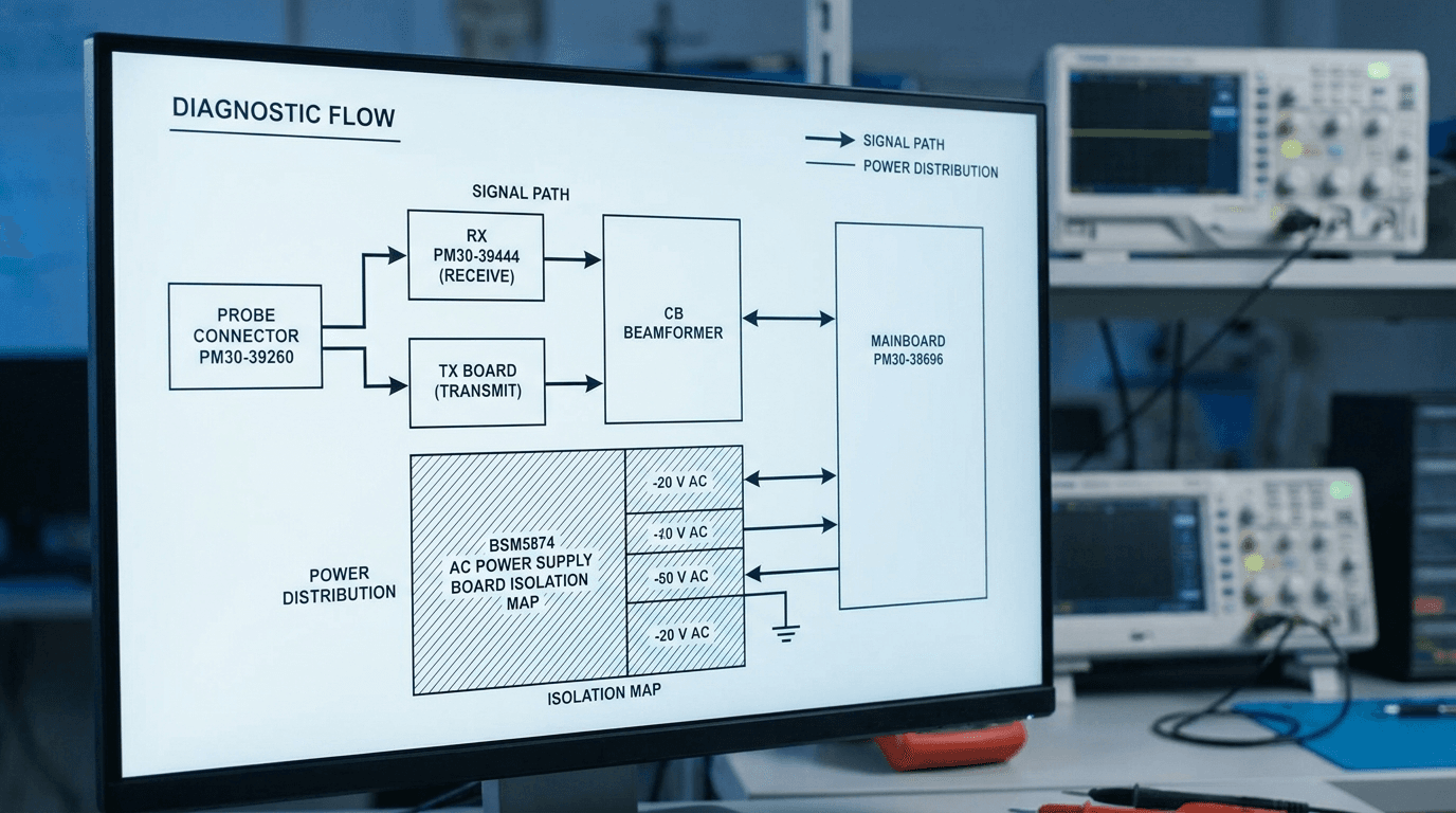
Introduction: Structured Board Isolation for Toshiba and Canon Aplio Ultrasound Platforms
Diagnostic ultrasound systems built on Toshiba and Canon Aplio technology represent a dominant cornerstone of global clinical imaging. From established premium workhorses like the Aplio 300, Aplio 400, and Aplio 500 (SSA-770A series) to mid-range consoles such as the Aplio MX (SSA-660A) and Xario series, up to the high-end Aplio i-series Prism line (i600, i700, i800, and i900), these systems integrate multi-channel front-end beamformers, high-density transducer receptacles, complex DC power regulation, and host computer processing boards.
When an Aplio console experiences hardware failure, biomedical equipment technicians (BMETs), hospital clinical engineering teams, and independent service organizations (ISOs) face a twofold challenge: systematically isolating the electronic failure to the precise printed circuit board assembly (PCBA), and navigating brand-label updates resulting from Canon Inc.'s acquisition of Toshiba Medical Systems Corporation in December 2016. A technician seeking a replacement receive board for an Aplio 500 or Aplio i800 may find identical OEM hardware carrying either a Toshiba or Canon part tag depending on the manufacturing year.
For medical device refurbishers, healthcare facilities, and biomedical engineering departments managing multi-vendor fleets, board-level component repair and verified board exchange offer a highly reliable, cost-effective alternative to full OEM system replacement. By establishing systematic symptom-to-board mapping and verifying exact PM30-series or BSM-series part numbers, service teams can eliminate trial-and-error part swapping, minimize clinical downtime, and safely maintain diagnostic precision.
For technical service decision paths covering other major multi-brand console lines, biomedical engineers can consult our sibling reports for GE ultrasound board-level symptom isolation, Philips iU22/EPIQ board symptom diagnosis, Siemens Acuson Sequoia/S2000 board symptom paths, and Hitachi / Fujifilm Aloka board symptom decision paths.
Which Aplio board causes no image, probe-not-detected, channel dropout or no-boot?
Before attempting chassis disassembly or component substitution, service engineers should categorize observed failure modes into four distinct hardware sub-systems: (1) Transducer Interface & Probe Selector Array, (2) Signal Acquisition & Beamforming Array (RX, TX, CB, FERX), (3) Back-End Mainboard & Host Processing Module, or (4) Main Power Conversion & Voltage Regulation Subsystem.
Electronic degradation across Toshiba and Canon Aplio systems follows specific hardware patterns: high-voltage pulsers on TX boards and low-noise pre-amplifiers on RX boards endure thermal cycling during high-power Color Doppler and PW Doppler modes; AC power supply modules experience capacitor degradation over prolonged clinical uptime; and probe connector receptacle pins suffer mechanical wear or fluid contamination.
Table 1 correlates observed clinical and hardware symptoms across Aplio 300/400/500, Aplio MX, Xario, and the Aplio i-series directly to suspected functional sub-systems, primary candidate board assemblies, and verified manufacturer part numbers from Rongtao Medical's catalog ground truth 4:
| Console Platform / SSA Series | Observed Hardware / Clinical Symptom | Suspected Functional Sub-System | Primary Candidate Board Assembly | Verified OEM Part Number |
|---|---|---|---|---|
| Aplio 500 (SSA-770A) | B-mode acoustic channel dropout; vertical black line artifacts | Receive Beamformer Array | RX Board Assembly | PM30-39444 (Catalog ID aplio-500-rx-pm30-39444) |
| Aplio 400 / 500 | 'Probe Not Detected' error on connected transducer port | Probe Interface & Relay Block | Probe Connector / Relay Board | PM30-39260 / Probe Relay Module |
| Aplio 300 / 400 / 500 | Console fails to boot; hangs at initial startup splash screen | Host Processing Mainboard | Mainboard Assembly | PM30-38696 |
| Aplio 300 / 400 / 500 | Transducer signal transmit noise & Color Doppler channel distortion | Transmit Beamformer Array | TX Board Assembly | PM30-38691 |
| Aplio 300 / 400 / 500 | Channel communication failure across analog acquisition front-end | Channel Bus Interconnect | CB Board Assembly | PM30-38693 |
| Aplio i800 | Multi-channel receive processing error; image shadow bands | Receive Signal Processor | RX-RC Board Assembly | PM30-41136 (Catalog ID aplio-i800-rx-rc-pm30-41136) |
| Aplio i700 | Receiver timing synchronization failure; loss of 2D image gain | Receive Control Board | RC Board Assembly | PM30-42844 (Catalog ID i700-rc-pm30-42844) |
| Aplio i600 / i700 / i800 | Console completely dead; zero LED activity or fan rotation | Main AC/DC Power Conversion | AC Power Supply Module | BSM5874 (Catalog ID i600-i700-i800-ac-power-supply-bsm5874) |
| Aplio i600 | Touch display digitizer intact but non-responsive to finger touch | User Interface Touch Controller | Touch Screen Digitizer Board | BSM34-5530 (Catalog ID i600-touch-screen-bsm34-5530) |
| Aplio i600 / i800 | Trackball stickiness & soft-key illuminated button freeze | Control Panel Interface | Control Panel with Trackball Assembly | BSM34-4188 / FLT20UG0-T2 (Catalog ID i600-i800-control-panel-with-trackball-bsm34-4188-flt20ug0-t2) |
| X200 / Xario 200 | Front-end transmit timing signal loss; TI board fault | Transmit Interface Subsystem | TI Board Assembly | BSM34-1914 (Catalog ID x200-ti-board-bsm34-1914) |
| Aplio MX (SSA-660A) | IO port communication error; peripheral & network interface fault | IO Interface Board | IO Board Assembly | SP01304 |
| Aplio 500 (SSA-770A) | Back-end image processing freeze; boot-loop or logo freeze | Back-End Processor | BE Board Assembly | 7472421 / PM30-30385 |
| SSA-550A / SSA-580A | Acoustic noise across the multi-channel front-end array; front-end sub-module fault | Front-End Transmit/Receive | TXBF / RXBF / FERX Board | BSM31-3097 (TXBF) / BSM31-3099 (RXBF) / BSM31-6413 (FERX) |
Source: Rongtao Medical photo-backed catalog rows (marked with Catalog IDs) and verified Toshiba/Canon inventory; additional OEM part numbers cross-referenced against OEM service documentation and Rongtao part-note records
How do I identify the correct Toshiba/Canon Aplio board part number and revision?
Accurate part identification is essential for Toshiba and Canon Aplio servicing because circuit board nomenclature follows specific OEM part numbering schemes across different platform generations:
- PM30-Series Part Numbers (Aplio 300/400/500 & i-Series): Standard Toshiba/Canon part codes for major board assemblies consist of the prefix
PM30-followed by a 5-digit numerical code (e.g.,PM30-39444for Aplio 500 RX,PM30-38696for Mainboard,PM30-41136for Aplio i800 RX-RC, andPM30-42844for Aplio i700 RC). Labels on the PCB silkscreen or barcode sticker specify the base part number and hardware revision letter. - BSM-Series Part Numbers (Power Supplies & i-Series Sub-Assemblies): Power supplies, touch screen assemblies, and interface boards often use the
BSMprefix (e.g.,BSM5874for Aplio i-series AC Power Supply,BSM34-5530for i600 Touch Screen,BSM34-4188for Control Panel with Trackball, andBSM34-1914for X200 TI Board). - SSA Platform Designation: Toshiba/Canon internal system platforms use an SSA model code:
SSA-770Acorresponds to Aplio 500,SSA-660Ato Aplio MX,SSA-790Ato Aplio XG,SSA-550Ato the Nemio series, andSSA-580Ato Nemio XG. Always verify both the commercial model name (e.g., Aplio 500) and the internal SSA designation (e.g., SSA-770A) when cross-referencing board documentation 5.
When requesting replacement modules or scheduling board repairs, biomedical engineers should photograph the paper barcode sticker and printed PCB silkscreen markings on both sides of the board. For detailed guidance on reading part labels and executing post-repair validation, refer to our comprehensive guide on ultrasound board part number verification and acceptance testing.
Are Aplio 300/400/500 and Aplio i-series (i600/i700/i800/i900) boards interchangeable?
A frequent question among service personnel is whether circuit boards from legacy Aplio systems (Aplio 300, 400, 500) can be swapped into newer Aplio i-series consoles (i600, i700, i800, i900). The short answer is no: Aplio 300/400/500 boards and Aplio i-series boards are not freely interchangeable.
Although both platform generations share the overarching Aplio brand identity, the i-series represents a major architectural upgrade in digital beamforming density, power bus distribution, and high-speed data interconnects:
- Beamformer Architecture: Legacy Aplio 300/400/500 systems utilize separate RX (PM30-39444), TX (PM30-38691), and CB (PM30-38693) channel board arrays. In contrast, the Aplio i-series employs integrated high-density RX-RC (PM30-41136 on i800) and RC (PM30-42844 on i700) signal processing modules capable of handling ultra-broadband transducer arrays.
- Power Supply Architecture: The i-series utilizes the BSM5874 AC power supply unit designed for modern high-efficiency power distribution, whereas older SSA-770A (Aplio 500) systems rely on dedicated multi-rail power supplies specific to legacy chassis frames.
- User Interface & Control: Control panel interfaces for the i-series (BSM34-4188 control panel with FLT20UG0-T2 trackball, BSM34-5530 touch screen) utilize updated capacitive touch controllers and serial communication buses that are incompatible with older resistive touch panels on Aplio 300/400/500.
Consequently, biomedical engineers must source exact generation-matched board part numbers. Swapping a legacy PM30-39444 RX board into an Aplio i700 console will cause mechanical fit mismatches, power connector pinout incompatibilities, and immediate system initialization errors.
Is the older Aplio 300/400/500 still serviceable after the Toshiba-to-Canon transition?
On December 19, 2016, Canon Inc. completed its acquisition of Toshiba Medical Systems Corporation (following the definitive agreement signed on March 17, 2016) 2. Toshiba Medical Systems Corporation was subsequently renamed Canon Medical Systems Corporation. This corporate transaction raised concerns among healthcare facilities regarding long-term serviceability and spare parts availability for older Toshiba-branded Aplio consoles.
To verify official regulatory continuity across this corporate transition, we analyzed primary FDA 510(k) Premarket Notification clearance records for the Aplio platform line 1. Table 2 traces the regulatory clearance timeline of the Aplio family across successive corporate applicant entities:
| FDA 510(k) Number | Clearance Date | Device / Software Name | Official Applicant Name | Corporate Lineage Era |
|---|---|---|---|---|
| K121422 | 2012-08-16 | APLIO 500/400/300 DIAGNOSTIC ULTRASOUND SYSTEM | Toshiba Medical Systems Corporation | Toshiba Medical Era |
| K161843 | 2016-09-21 | Aplio i900/i800/i700 Diagnostic Ultrasound System, V2.0 | Toshiba Medical Systems Corporation | Toshiba Medical Era |
| K173090 | 2018-01-11 | Aplio i900/i800/i700/i600 Diagnostic Ultrasound System, V2.4 | Toshiba Medical Systems Corporation | Toshiba Medical Era |
| K191663 | 2019-09-18 | Aplio a550, Aplio a450 and Aplio a Diagnostic Ultrasound System, V4.0 | Canon Medical Systems Corporation | Canon Medical Era |
| K253597 | 2026-01-20 | Aplio beyond and Aplio me Software V2.0 | Canon Medical Systems Corporation | Canon Medical Era |
Source: FDA 510(k) Premarket Notification Database (Official FDA clearance records)
The regulatory record demonstrates seamless continuity: the official 510(k) applicant name shifted from Toshiba Medical Systems Corporation to Canon Medical Systems Corporation between January 2018 (K173090) and September 2019 (K191663). Latest clearances such as K253597 (cleared January 20, 2026 for 'Aplio beyond' and 'Aplio me' software V2.0) confirm that Canon actively maintains and expands the Aplio diagnostic ecosystem.
From a practical service standpoint, legacy Aplio 300, 400, and 500 consoles remain fully serviceable through independent service channels. Because the fundamental hardware design was established prior to the acquisition, tested replacement boards bearing original Toshiba PM labels continue to function identically alongside newer Canon-labeled parts. Independent board repair and stock availability allow clinical facilities to extend the operating life of their Aplio fleets well beyond OEM end-of-life notices. For strategic advice on evaluating repair versus replacement options, see our analysis on ultrasound board repair vs replacement decision frameworks.
What does 'probe not detected' mean on a Toshiba Aplio 500, and is it always a board fault?
The error message 'Probe Not Detected' or 'No Transducer Connected' on an Aplio 500 or Aplio i-series console is one of the most common service calls. While technicians often suspect a broken probe or damaged cable, the root cause can lie in the probe connector board (PM30-39260), probe selection relays, or pin receptacle blocks.
To isolate the fault accurately before condemning an expensive transducer or ordering a replacement probe-connector board, follow this 4-step diagnostic decision tree:
- Step 1: Cross-Port Swap on Same Console: Move the suspect probe from Port 1 to Port 2 or Port 3. If the probe is recognized immediately on Port 2 but fails on Port 1, the transducer itself is functional. The fault resides in Port 1's receptacle pin block or the probe selection relay circuit on Probe Connector Board PM30-39260.
- Step 2: Cross-Console Probe Validation: Connect the suspect probe to a second compatible Aplio console. If the probe fails to be detected on any console, the issue is within the probe connector housing, ID EEPROM chip, or cable wiring. Consult our guide on ultrasound probe repair vs replacement or send the unit to Rongtao's probe repair facility.
- Step 3: Multi-Probe Console Test: Connect multiple known-good probes to all console ports. If 'Probe Not Detected' appears across all ports simultaneously, the probe identification power rail (+5V ID supply) or main probe-connector interface board has failed.
- Step 4: Physical Connector Inspection: Inspect the console probe port connector pins under magnification for bent, recessed, or oxidized pins. Fluid ingress from coupling gel can short ID sense pins, tricking the console into reporting a missing probe.
Is a no-boot, freeze or power loss on an Aplio system an AC PSU or mainboard failure?
When an Aplio 300/400/500 or Aplio i-series console fails to start up, freezes at the loading screen, or repeatedly reboots during operation, service personnel must differentiate between main power supply (PSU) issues and mainboard/motherboard processing failures.
Technicians should evaluate the following structural diagnostic paths:
- Total Power Deadness (No LEDs, No Fan Rotation): Check facility AC power and line cords first. If wall voltage is confirmed, measure DC standby voltage (+5VSTB) output from the AC Power Supply (e.g., BSM5874 on i-series or BSM31-4472 on SSA-660A). Absence of standby voltage implicates internal AC fuses or primary switching transistors in the PSU.
- Instant Power Off / Circuit Breaker Trip: If the console momentarily powers on for 1–2 seconds and then shuts down with an audible relay click, a short circuit exists on a high-voltage DC supply rail (+100V/-100V transmit rails). Over-current protection in the PSU shuts down power to protect beamformer circuitry. Disconnect TX boards (PM30-38691) sequentially to isolate the shorted board.
- Freeze at Aplio Splash Screen: If power fans run normally and status LEDs illuminate green but system boot halts at the loading screen, power rails are healthy. The failure is isolated to the Mainboard Processor (PM30-38696 on Aplio 300/400/500, BE board 7472421 on SSA-770A / Aplio 500), system RAM, or corrupted boot storage. For broader insights into power and boot failures across console brands, see our technical report on ultrasound power supply failure and boot loop diagnosis.
Where does Rongtao's Toshiba/Canon support start and stop — and what evidence must I collect for a quote?
Rongtao Medical serves as a specialized independent service provider and global distributor of multi-brand ultrasound repair parts and board-level solutions. In strict accordance with FDA medical device servicing frameworks 6, Rongtao's board repair and exchange processes restore original circuit functionality without altering OEM device design or intended clinical application.
Rongtao offers comprehensive board-level component repair, advance exchange modules, and fully tested replacement inventory for Toshiba and Canon Aplio systems. Our technical service operations deliver a standard 5-to-8 business day board repair turnaround, rigorous 48-hour live-console stress testing on dedicated Aplio test frames, and a standard 90-day warranty across all repairs and inventory parts 4.
To explore our verified catalog of Toshiba/Canon parts, visit our Rongtao Toshiba support hub, browse tested items in the Rongtao Parts Catalog, review our quality standards on Rongtao Quality Systems, or contact our engineering support team via Rongtao Medical Contact Engineering.
When requesting a Toshiba or Canon Aplio board repair or replacement quote, please submit: (1) Exact system model and SSA platform designation (e.g., Aplio 500 / SSA-770A, Aplio i800, Aplio MX / SSA-660A), (2) Manufacturer part number and revision suffix from the board label (e.g., PM30-39444, PM30-41136, BSM5874), (3) High-resolution photographs of both sides of the board including paper barcode stickers, (4) Detailed description of observed symptoms or error codes, (5) Quantity required, and (6) Destination country for accurate freight and delivery estimates.— Rongtao Medical Repair & RFQ Protocol