
What Should a "Real-Machine Tested" Evidence Pack Contain for a Repaired Board?
When an independent service organization (ISO), hospital healthcare technology management (HTM) team, or medical equipment distributor receives a repaired ultrasound circuit board—such as a GE Voluson E8 RFM board, a Philips EPIQ 7 ACQ acquisition module, or a Siemens Acuson S2000 beamformer—the phrase "fully system tested" on a packing slip is legally and technically insufficient 78. Under modern quality management frameworks including ISO 13485:2016 (Clause 7.4.3 for verification of purchased product and Clause 8.2.6 for monitoring and measurement of product) and the U.S. FDA Quality Management System Regulation (QMSR, 21 CFR Part 820) 23, purchasing controls require auditable evidence that a repaired or refurbished component meets its functional specifications before installation into a clinical system.
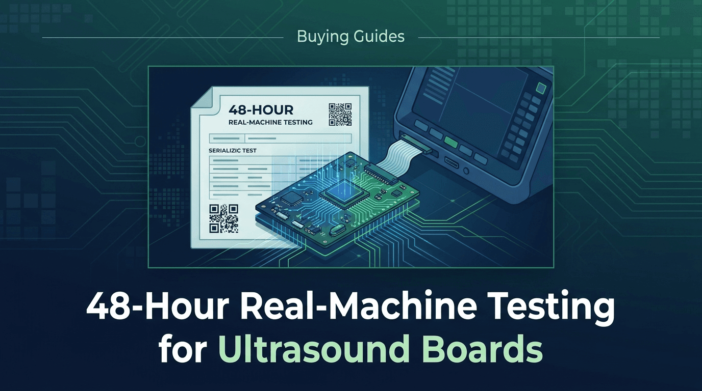
A complete, serialized Real-Machine Test Evidence Pack converts an unverified marketing assertion into a traceable quality record. It bridges the gap between component-level bench repair and clinical scanner deployment. Rather than accepting generic checkboxes, buyers should mandate a standardized test-record deliverable covering eight core data blocks:
- Asset & Board Identity Chain: Customer identity, work order number, board description, OEM part number, bare PCB silkscreen revision, top assembly revision sub-suffix, and unit serial number.
- Test-Host Scanner Identity: Exact OEM system make, model family, console serial number, installed system software release version, and active software options present during testing.
- Incoming Fault & Baseline Record: Documented customer-reported symptom (e.g., color Doppler noise artifacts, high-voltage rail shutdown, channel dropouts) and initial bench baseline measurements.
- Authorized Work Scope: Summary of component-level repairs performed (e.g., high-voltage MOSFET replacement, FPGA reballing, capacitor bank refresh, trace restoration).
- Tiered Test Battery Execution: Chronological record of bench checks, compatible-host real-machine functional testing, and controlled phantom or diagnostic checks executed.
- Soak Duration & Interruption Log: Continuous operational time inside the host system (e.g., 48 hours continuous load), ambient temperature, active thermal monitoring log, and any logged boot interruptions or diagnostic restarts.
- Before & After Verification Artifacts: Side-by-side system diagnostic logs, self-test results, voltage rail measurement captures, and high-resolution photo/video evidence of system operation.
- Acceptance Criteria & Release Authority: Quantitative pass/fail criteria, date and timestamp of completion, operating technician signature, and authorized Quality Assurance release sign-off.
To prevent document tampering and ensure full traceability, this evidence pack should be issued with a unique serial hash linked to the physical board label. Buyers can integrate this requirement directly into purchase orders or repair service agreements using the standardized schema outlined below.
| Evidence Section | Mandatory Data Fields | Auditable Deliverable / Artifact | Verification Purpose |
|---|---|---|---|
| 1. Board Identity | Part Number (PN), Assembly Rev, PCB Rev, Unit Serial Number (SN) | High-res photo of OEM label, barcode & serial sticker | Prevents revision mismatch & fake serial labeling |
| 2. Test-Host Config | Host Model, Host SN, Software Version, Installed Options | System status screenshot / diagnostic config export | Proves board was tested in compatible host environment |
| 3. Work Scope | Incoming symptom, replaced components, PCB trace work | Repair traveler log & micro-soldering inspection photo | Establishes component traceability & repair scope |
| 4. Functional Test | Modes exercised (B, M, Color, PW/CW, 3D/4D), Probe IDs used | Mode screenshots, acoustic channel diagnostic output | Verifies signal path integrity across operational modes |
| 5. 48-Hour Soak | Start/end timestamp, total continuous hours, thermal logs | Automated system status log / video soak recording | Catches thermal drift, intermittent drops & boot instability |
| 6. Release Gate | Pass/Fail status, QA Sign-off, Date, Technician ID | Signed & stamped serialized Quality Release Certificate | Establishes regulatory accountability & warranty start |
Source: Rongtao Medical Quality Assurance & Service Engineering Standard (2026)
How Do Bench, Compatible-Host Real-Machine, and Phantom Test Tiers Differ?
A common point of confusion among procurement officers and HTM managers is assuming that any laboratory testing constitutes "real-machine testing". In practice, component-level board testing falls into distinct technical tiers, each providing different levels of risk reduction. Understanding these boundaries is critical when evaluating vendor capabilities 48.
| Test Tier | Testing Environment | What It Detects | What It Misses | Verification Level |
|---|---|---|---|---|
| Tier 1: Bench Fixture | Stand-alone power supply & oscilloscope / multimeter fixture | Short circuits, blown fuses, basic power rail voltages, clock signals | FPGA firmware boot errors, bus communication, image processing, thermal drift under load | Basic Hardware Integrity |
| Tier 2: Real-Machine Functional Host | Installed in compatible actual OEM ultrasound console | Bus communication failures, system software loading errors, mode switching faults, UI control errors | Transducer acoustic beam degradation, micro-element dropout | System Functional Compatibility |
| Tier 3: Phantom & Controlled Imaging | Real machine paired with calibrated tissue-mimicking phantom & probe | Channel sensitivity imbalance, image artifacts, Doppler shift accuracy, noise floor spikes | Finished-system electrical safety ground leakage, long-term capacitor aging | Clinical Image Quality & Signal Integrity |
| Tier 4: Return-to-Service Safety Gate | Fully assembled host system tested with calibrated safety analyzer | Chassis leakage current, patient applied part isolation, ground bond resistance | Board-level internal silicon degradation | Finished-Device Safety Compliance (IEC 60601-1) |
Source: Biomedical Engineering & Quality Verification Matrix
Tier 1 bench testing is a necessary step during initial component replacement, but it cannot simulate the complex bus interactions, dynamic power draw, high-speed data serialization, and thermal conditions of a live scanner console. For example, a transmit/receive (TX/RX) board may pass static bench voltage checks but trigger immediate high-voltage shutdown or channel dropout when switching from 2D B-mode to high-PRF Color Doppler in a live host. For comprehensive receiving acceptance, buyers should reference our guide on ultrasound board part-number verification and acceptance testing.
Which Real-Machine Test Battery Matches Each Board Function?
Different circuit boards within an ultrasound system perform radically different technical tasks. A transmit beamformer requires high-voltage pulse modulation, whereas a host CPU motherboard handles operating system execution and DICOM networking. Consequently, a universal "one-size-fits-all" test sequence cannot thoroughly validate every board type. A defensible evidence pack must detail the specific functional test battery corresponding to the board assembly class 1.
| Board Assembly Class | Representative OEM Board Examples | Key Real-Machine Test Battery Steps | Critical Verification Artifacts |
|---|---|---|---|
| Receive/Transmit (TX/RX) Front-End | GE Voluson RFM / RFM423, Philips EPIQ ACQ, Siemens Acuson TR Board | High-voltage pulse timing, probe connector relay switching, multi-probe port select, low-noise pre-amp check across low/high frequency probes | Channel noise spectrum diagnostic log, transducer connector relay test record, Color/PW Doppler signal-to-noise ratio check |
| Beamformer (BF / DBM) | GE Logiq E9 DBM64 / BF64, Philips iU22 BF Board, Mindray DC-8 BF | Digital delay alignment, dynamic receive focusing sweep, beam delay calculation verification, 64/128-channel element summing test | System built-in self-test (BIST) beamformer report, element channel uniform sensitivity plot |
| Power Supply Unit (PSU / HV) | GE Voluson E8 Power Box, Philips EPIQ Power Subsystem, Toshiba Aplio PSU | Multi-rail DC output under maximum transmission load, high-voltage (+/-100V) step accuracy, thermal soak at continuous high PRF | Voltage rail stability telemetry log, thermal camera image / temperature log, ripple voltage oscillogram under load |
| Control Panel / UI / Trackball | GE Vivid E9 User Interface Board, Philips iE33 Control Board, Aloka F75 UI | TGC slide pot linear response check, encoder knob detent counting, key matrix actuation test, trackball quadrature signal verification | UI diagnostic button matrix test pass report, TGC curve response log |
| Motherboard / Host CPU / Back-End | GE Logiq P5 Motherboard, Philips CX50 Host Controller, Samsung Accuvix CPU | Cold boot reliability (10 consecutive cycles), PCIe bus speed negotiation, GPU rendering under 4D volume stress, DICOM export test | System BIOS POST log, OS event log clean export, stress-test frame rate stability log |
| I/O & Display Video Board | GE Voluson E10 Video Processing Board, Philips HD11 AVIO Board | Multi-monitor output resolution (HDMI/DVI/DisplayPort), ECG trigger signal input, audio channel line-in/out clarity check | Color bar pattern generator screenshot, ECG synchronization signal trace |
Source: Rongtao Medical Component-Level Engineering Protocol
When evaluating repair vendors, HTM leaders should ensure the vendor maintains dedicated OEM test consoles representing these exact architecture families. For details on auditing repair shop infrastructure, see our report on qualifying a component-level ultrasound board repair provider.
What Red Flags Expose a Vague "Fully Tested" Stamp Versus a Defensible Test Record?
In the secondary ultrasound parts marketplace, many suppliers affix shiny stickers reading "100% Tested", "Passed QC", or "System Verified". However, without accompanying documentation, these stickers carry zero technical or regulatory weight. Table 4 compares red-flag supplier practices against robust, auditable evidence standards 37.
| Unsubstantiated Supplier Claim | Technical Risk / Potential Defect | Auditable Evidence Required from Supplier | Acceptance Verdict |
|---|---|---|---|
| "Tested on a real machine prior to stock listing" | Board was tested months/years ago in an unknown system; ambient storage may have degraded capacitors or ESD damaged components | Date-stamped test report completed within current repair or fulfillment window with serial number matching board | REJECT without current serialized report |
| "Passed full bench diagnostic sweep" | Board was powered on a static test bench without dynamic system load, probe transducers, or thermal enclosure | Tier 2/3 real-machine functional test record detailing active probe models and modes exercised | REJECT for high-level beamformer/TX-RX boards |
| "100% Tested and Guaranteed Working" | Generic marketing catchphrase with no recorded metrics, voltage logs, or tester identity | Serialized evidence pack containing before/after diagnostic logs, voltage telemetry, and QA release signature | REJECT without serialized pack |
| "Original OEM Factory Condition / OEM Equivalent" | Misleading terminology that implies OEM authorization or new component status without provenance proof | Clear condition grade disclosure (Repaired, Refurbished, Tested-Used) with component replacement log | REJECT misleading OEM equivalence claims |
| "Tested for 1 hour with no errors" | Insufficient duration to uncover thermal intermittent dropouts that occur after 4 to 12 hours of operation | Continuous 48-hour real-machine thermal soak log without unhandled system exceptions or restarts | REJECT short-soak high-value board claims |
Source: Ultrasound Procurement Quality Audit Framework
For a comprehensive understanding of part condition definitions and documentation standards, buyers can consult our guide on ultrasound parts condition grades and acceptance evidence.
What a 48-Hour Real-Machine Test Can Prove—and What It Cannot Prove
Rongtao Medical’s standard quality protocol mandates a 48-hour real-machine test inside an actual ultrasound system for every repaired circuit board prior to release 1. While this protocol provides industry-leading confidence, quality transparency requires clearly articulating both the power and the boundaries of a 48-hour load test.
What a 48-Hour Real-Machine Test SUBSTANTIATES:
- Thermal Stability & Heat Dissipation: Electronic components (especially power MOSFETs, high-voltage drivers, and FPGA processors) generate significant heat. A 48-hour soak validates that heat sinks, thermal paste, and cooling pathways dissipate thermal loads without triggering thermal shutdown or parametric drift.
- Intermittent Fault Suppression: Intermittent solder joint fractures, micro-cracks in multi-layer PCBs, and failing electrolytic capacitors frequently manifest only after several hours of continuous thermal cycling. A 48-hour test successfully catches these latent failures.
- Cold & Warm Boot Consistency: Repeated automated reboot cycles during the 48-hour period verify that the board’s power-on reset (POR) circuits, bootloader ROMs, and PCIe handshake routines initialize consistently across operational state changes.
- Operating System & Diagnostic Log Cleanliness: Continuous execution allows monitoring of system event logs to confirm zero unhandled bus exceptions, memory leaks, or background diagnostic faults occur under extended operation.
What a 48-Hour Real-Machine Test CANNOT Prove (Important Boundaries):
- Future Field Mean Time Between Failures (MTBF): A 48-hour successful test proves zero defects during the test window; it cannot mathematically guarantee that an unreplaced 10-year-old adjacent capacitor will not fail 6 months later in the field.
- Finished-System Electrical Safety (IEC 60601-1 / IEC 62353): Testing a board inside a laboratory host scanner verifies the board's functional logic, but it does NOT certify the electrical safety of the end-user’s hospital scanner. The hospital HTM team must perform chassis ground bond and patient leakage current testing on the complete system after board installation 5.
- Transducer Acoustic Output & Beam Calibration: A real-machine board test verifies signal processing, but it cannot measure absolute acoustic intensity (ISPTA/MI/TI) or hydrophone acoustic beam profiles. Acoustic probe calibration remains governed by specialized probe acceptance testing protocols 4 (see our report on ultrasound probe acceptance testing).
- Universal Cross-Model Compatibility: Testing a board in a GE Logiq E9 Revision R5 host scanner proves functionality for Revision R5; it does NOT prove the board will function in a Revision R1 or R6 console without software/firmware matching.
- OEM Authorization or Regulatory Product Approval: Real-machine functional testing by an independent repair facility verifies technical performance; it does NOT constitute OEM authorization, nor does it imply FDA approval of the repair process 26. For regulatory definitions, consult our analysis on which standards matter for ultrasound parts.
A Quote and PO-Ready Test-Record Schedule for Buyers
To ensure your organization receives auditable evidence for every board repair or replacement transaction, incorporate the following contract clause directly into your purchase orders, RFQ documents, and service agreements:
Mandatory Board Test Evidence Schedule: Vendor shall provide a serialized, unit-specific Real-Machine Test Evidence Pack for every repaired or exchange circuit board delivered under this Agreement. The Evidence Pack shall include: (a) high-resolution photographs of the physical board label displaying the exact OEM Part Number, PCB Revision, and Serial Number; (b) identification of the compatible OEM test-host model, serial number, and software version used; (c) a summary of component-level repairs performed; (d) a minimum 48-hour continuous real-machine load/thermal test record with zero unhandled system errors; (e) mode-specific functional diagnostic verification; and (f) a signed Quality Assurance Release Certificate detailing technician ID and pass date. Delivery without a complete Evidence Pack shall constitute a non-conforming shipment subject to immediate RMA rejection at Vendor expense.— Standard B2B Biomedical Procurement Clause (Rongtao Recommended Schedule)
Where Rongtao Fits—and Where It Does Not
At Rongtao Medical, our operational model is built on technical transparency and engineering rigor 1:
- Where We Fit: We specialize in multi-brand component-level ultrasound circuit board repair (GE, Philips, Siemens, Toshiba/Canon, Mindray, Aloka) and tested replacement board supply. Every repaired board undergoes a full 48-hour real-machine soak inside an actual ultrasound system in our 3,000 m² Guangzhou technical center before release. High-resolution photo and video evidence, along with a serialized repair report, is provided with each completed order. Standard board repair turnaround is 5 to 8 business days, backed by a typical 90-day warranty.
- Where We Do Not Fit: Rongtao Medical does not claim to be an authorized OEM service center or representative for GE, Philips, or Siemens. We do not provide on-site hospital field service or final clinical return-to-service electrical safety certification under IEC 60601-1 (which must be performed by the hospital biomedical engineer on the host system). Furthermore, our 48-hour real-machine board testing protocol applies specifically to repaired circuit board assemblies—it should not be conflated with probe relensing or un-tested as-is parts sales.
For urgent parts inquiries, component availability, or to request a serialized board repair evaluation, visit our parts catalog, learn about our repair process, review our quality assurance standards, or contact our engineering team with your exact board part number, revision sub-suffix, photos of both board sides, and host system model.