
Which ACUSON S-family board domain does my symptom point to?
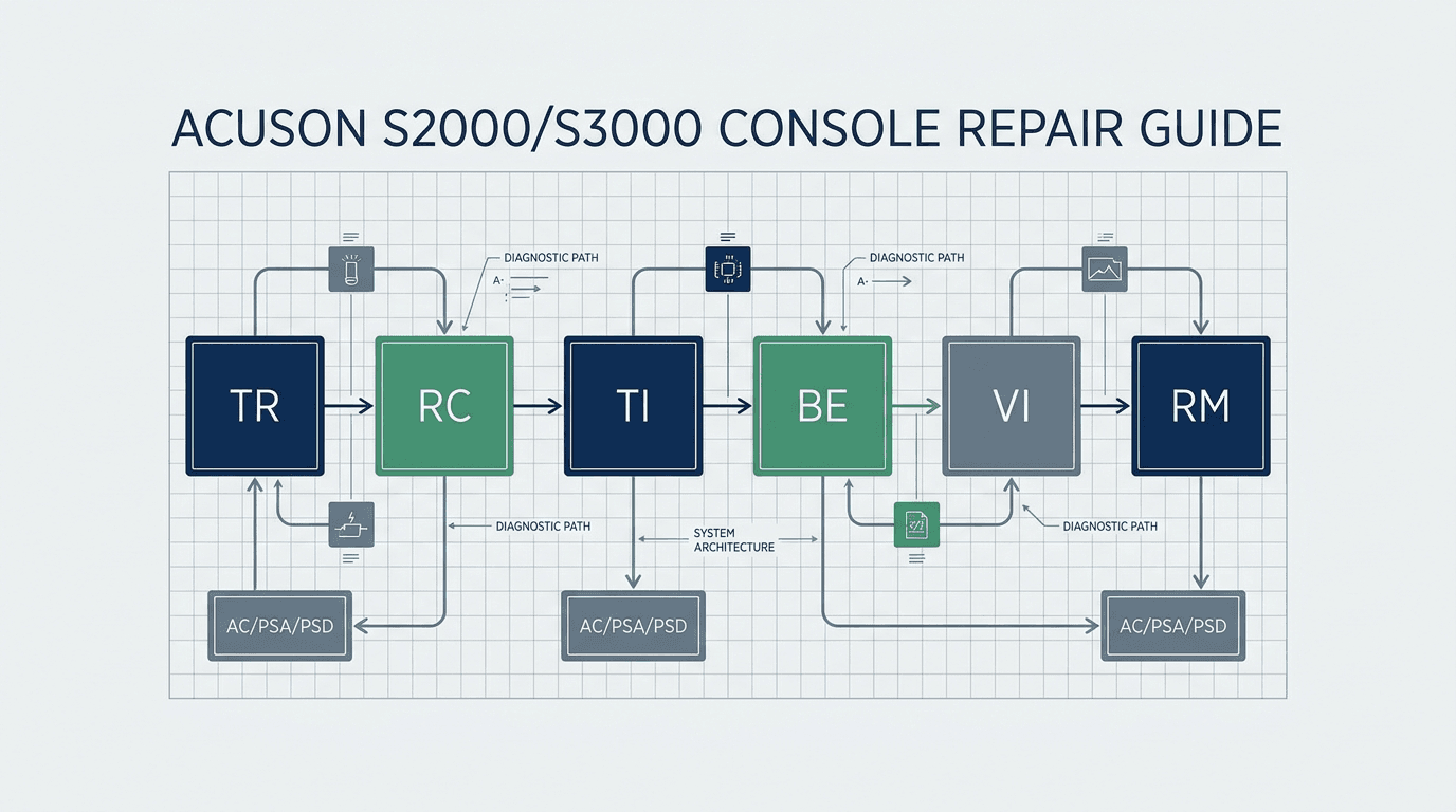
The Siemens ACUSON S-family — comprising the S1000, S2000, S3000, and their Automated Breast Volume Scanner (ABVS) configurations — was engineered around a modular, card-cage architecture. Unlike compact or portable scanners that integrate processing onto a single master motherboard, the S-family partitions acquisition, signal processing, power transformation, and user interaction into distinct hardware cards housed in the lower chassis card cage and power bay 9. Diagnosing a down system begins by categorizing the observed failure into one of four primary hardware domains:
- Acoustic Front-End Domain (TR / RC / TI): Responsible for high-voltage pulse transmission, transducer multiplexing, acoustic beam steering, and initial analog-to-digital signal conversion. Faults manifest as total loss of acoustic echo across all probes, vertical dropout bands, or missing scan lines.
- Digital Back-End Processing Domain (BE / VI / RM): Responsible for radio-frequency (RF) data demodulation, cine memory buffer management, scan conversion, graphic overlay rendering, and host CPU system timing. Faults manifest as boot loops, operating system freezes, video artifacting, or Doppler spectral distortion.
- Power Conversion & Distribution Domain (AC / PSA / PSD): Converts mains AC power into regulated low-voltage digital rails and programmable high-voltage analog rails for the beamformers. Faults manifest as complete no-power states, immediate breaker tripping, or spontaneous restarts under heavy acoustic loading.
- Control & User Interface Domain (CB / CP / IO): Manages keyboard scanning, trackball encoders, touch-screen communications, peripheral video outputs, and external DICOM Ethernet interfaces. Faults manifest as unresponsive control panels, frozen trackballs, or network communication drops.
The following diagnostic decision table maps high-frequency clinical and technical symptoms to their probable board domains, key differential checks, and verified replacement part numbers maintained in the Siemens parts inventory 15.
| Observed System Symptom | Primary Suspect Domain | Key Candidate Boards & Part Numbers | Differential Gating Step | Secondary Root Cause |
|---|---|---|---|---|
| Repeated restart / boot loop (reboots during Siemens splash screen) | Back-End Processing / Video Interface | VI Board (10435338), RM Module (10439172 / 10852163), BE Board (7472421) | Check AC power LED on lower chassis; if steady green, isolate VI and RM boards before condemning power supply | Corrupted system software drive or unstable PSA +5V rail |
| Random auto-shutdown after 20–40 min of normal scanning (no error code) | Back-End CPU / Thermal Management | Real Time Manager (RM) board (10439172 / 10853882 / 10854749) | Inspect chassis air filters and intake fans for dust blockage; check RM heatsink surface temperature | Failing DC cooling fan tray or thermal trip in PSA power supply |
| Total loss of 2D acoustic echo on ALL transducers (dark image field) | Front-End Transmit / Interface | TR Board (7475028 / 10853438), TI Board (10855828), High-Voltage PSU (07303659) | Test at least two distinct probe types (convex and linear) in different ports; check high-voltage transmit rail | TI transducer socket pin damage or beamformer sync bus failure |
| Vertical black bands / missing acoustic lines (fixed location across depth) | Front-End Receive / Processing | RC Board (7466043 / 10439476 / 7476810), TR Board (7475028) | Perform air-scan transducer test; swap probe to alternate port to rule out probe element failure | Damaged transducer connector pins or TI interface multiplexer relay |
| Color Doppler distortion / severe background noise / pulse inversion artifacts | Back-End Demodulation / Receive | RM Board (10439172), RC Board (10439476), BE Board (7472421) | Verify B-mode image quality; if 2D is clean but Color/PW Doppler fails, isolate RM/BE demodulation circuitry | External electromagnetic interference (EMI) or defective CW pen probe |
| Completely dead system (no fans, no LEDs, no power-button response) | Mains Power Conversion | AC Power Supply (10439494), PSA Power Supply (07846681 / 10440226) | Verify wall outlet voltage; measure AC line filter output; check primary circuit breakers on rear panel | Power switch harness break or Control Board (CB) standby rail fault |
| Control panel unresponsive / frozen trackball / dead sub-display | User Interface / Control Logic | Control Panel ASSY (10436217), CB Board (10439482/10439481), IO Board (10854778) | Check if USB peripheral mouse functions; verify trackball optical sensor cleanliness and 5V USB bus | Damaged ribbon cable between lower card cage and upper console |
| Acoustic Radiation Force (ARFI) / Virtual Touch calculation error | System Software / Calculation Engine | BE Board (7472421 / 11147269), System Software Patch Level | Cross-reference FDA recall Z-2321-2015 for the Virtual Touch IQ measurement correction | Uncalibrated 9L4 / 4C1 transducer or acoustic lens delamination |
Source: Rongtao Medical Technical Service Archive & Parts Catalog Records (2026)
Understanding this domain structure prevents the most common procurement error: ordering an expensive power supply when a back-end logic board is freezing the boot bus, or replacing an acoustic front-end board when a single transducer has broken coaxial lines 11.
Repeated restarts or boot loops: front-end, VI board or power? A documented S2000 case
One of the most disruptive failure modes encountered by clinical engineering teams on the Siemens ACUSON S2000 is the cyclic restart or boot loop. The operator powers on the scanner, cooling fans spin up, the front control panel indicators illuminate, and the Siemens boot animation appears on the primary display. However, shortly after the boot sequence begins, the console abruptly resets and repeats the cycle indefinitely 12.
When faced with a boot loop, field engineers frequently assume that the primary power supply (AC/PSA) has collapsed or that the Real Time Manager (RM) CPU has failed. However, documented service records in Rongtao Medical's technical archive reveal a more nuanced diagnostic path 16.
Documented Rongtao Service Case Analysis (S2000 Startup Failure):
An ACUSON S2000 experienced repeated reboots upon startup, unable to enter clinical scanning mode. Initial inspection confirmed that the AC main power indicator showed no abnormality through the restart cycles, ruling out an incoming mains collapse or primary AC breaker trip. In the S2000 architecture, the electronic system module partitions into the TR, CB, RC, BE, VI, and RM boards. The RM board acts as the Real Time Manager CPU board. Substituting the RM board did not resolve the boot loop. Systematic isolation of the back-end processing boards revealed that replacing the Video Interface (VI) board (catalog P/N 10435338) completely eliminated the restart cycle. The system then passed a one-hour post-repair run test and returned to normal use without recurrence.— Rongtao Medical Service Archive Case Record (siemens-s2000-color-doppler-startup-failure-maintenance)
Why does a Video Interface (VI) board failure cause a full system reboot rather than a blank screen? In a card-cage architecture like the S-family back-end, the VI board is not merely a passive display adapter — it participates in the back-end's synchronized communication with the host controller. During power-on self-test, the host expects each back-end board to complete its initialization handshake; a board that fails to acknowledge can stall or destabilize the boot sequence, and the system controller responds by resetting the chassis. The documented case above is consistent with that pattern: the fault presented as a restart loop, and the reset disappeared only when the VI board was replaced.
To isolate a boot loop systematically before ordering boards, follow this three-stage verification gate:
- Gate 1 (Mains & Power Rail Verification): Observe the rear and front AC power LEDs during the restart. If the LED flickers or turns amber/red, measure the +5V standby and +12V DC rails from the PSA power supply (07846681). If all voltage rails remain within ±2% tolerance during the reboot, the power subsystem is healthy. For detailed power supply testing procedures, consult the ultrasound power-supply failure decision path.
- Gate 2 (Peripheral & Transducer Disconnection): Power down the chassis completely, disconnect all ultrasound transducers from the TI board, and unplug all external USB peripherals, network cables, and video recorders. Power on the system. If the boot loop persists with zero transducers attached, the fault is confirmed within the console card cage.
- Gate 3 (Back-End Logic Isolation): If access to test modules is available, systematically reseat and test the back-end processing cards in sequence: RM CPU module (10439172), VI board (10435338), and BE back-end board (7472421). The documented S2000 case followed exactly this order — the RM substitution changed nothing, and the fault cleared only at the VI board 16.
Random auto-shutdown after 20-40 minutes: dust and thermals first, then the RM board — a documented S2000 case
A second prevalent failure mode on the ACUSON S2000 is the delayed automatic shutdown. A clinician begins an examination, the system initializes perfectly, 2D and color Doppler imaging perform to specification, but after approximately 25 to 40 minutes of continuous scanning, the machine suddenly shuts down completely without displaying any software error message or temperature warning on the screen 11.
Because modern ultrasound systems utilize thermal sensors throughout the card cage, a delayed shutdown is almost always triggered by an over-temperature protection circuit or thermal runaway in a high-density processing module. Field engineers must distinguish between environmental/airflow restrictions and component-level semiconductor breakdown 16.
Documented Rongtao Service Case Analysis (S2000 Auto-Shutdown):
An ACUSON S2000 shut down automatically after approximately 30 minutes of routine clinical use without error messages. Initial service inspection identified heavy dust accumulation across the internal chassis and card cage cooling channels. After complete cleaning and dust removal, the system was re-tested; the shutdown recurrence delayed to approximately 60 minutes, confirming a severe thermal dissipation dependency. During board-level isolation, handling checks found the Real Time Manager (RM) board running markedly hot. Replacing the RM module (catalog P/N 10439172) completely eliminated the auto-shutdown fault through an afternoon of post-repair testing.— Rongtao Medical Service Archive Case Record (maintenance-siemens-acuson-s2000-fault-maintenance-case-2)
The Real Time Manager (RM) module acts as the computational nerve center for the ACUSON S-family architecture. It hosts high-speed DSP arrays, dedicated microprocessors, and local buck-converter power regulators that generate low-voltage, high-current logic rails directly on the card. As these boards age, capacitor dielectric dry-out and thermal paste degradation increase internal resistance, causing the onboard voltage regulators to operate at elevated junction temperatures. Under sustained acoustic processing workloads, the regulator reaches its thermal cut-off limit, dropping the core voltage rail and forcing an instant chassis-level shutdown.
When troubleshooting progressive thermal shutdowns on an S1000, S2000, or S3000, execute the following staged protocol:
- Step 1 (Intake Filter & Fan Inspection): Remove the bottom and rear washable foam air filters. If clogged with lint or ultrasound gel residue, wash and dry them thoroughly. Verify that all chassis cooling fans in the bottom tray and power supply module rotate freely without bearing noise or speed oscillation.
- Step 2 (Chassis Cleanliness & Airflow Verification): Open the side card-cage covers and inspect the card guide channels. Use an ESD-safe vacuum and clean compressed air to remove accumulated dust from heatsink fins on the TR, RC, BE, and RM boards.
- Step 3 (Stress Testing & Thermal Timing): Boot the system in color Doppler mode on a phantom or active transducer. Record the exact elapsed time until shutdown. If the shutdown time increases significantly after cleaning (e.g., extending from 25 minutes to 60 minutes) but still occurs, component degradation on the RM board or PSA power supply is confirmed.
- Step 4 (Board-Level Isolation): Swap the RM module (10853882 / 10439172 / 10854749 depending on generation). If the system maintains continuous operation past 4 hours under full color Doppler acoustic output, the fault is isolated to the RM board.
Which boards are shared between S2000 and S3000 — and which are generation-specific?
A major source of confusion in independent servicing and parts procurement is determining hardware compatibility between the ACUSON S2000 (introduced under FDA 510(k) K072786 in 2007) and the higher-tier ACUSON S3000 (introduced under K121138 in 2012) 1 2. Third-party part listings frequently advertise boards as fitting 'S2000 / S3000' interchangeably, leading to costly procurement returns and extended system downtime when incompatible modules arrive 13 14.
Based on verified physical part inventories and engineering tear-downs at Rongtao Medical, S-family modules fall into two distinct categories: cross-platform shared modules and generation-locked modules 15.
1. Verified Cross-Platform Shared Modules (S2000 & S3000):
Live inventory records confirm that specific sub-assemblies carry dual-model factory labels and operate interchangeably across S2000 and S3000 chassis running compatible software levels:
- RC Receive Controller Board (P/N 10439476): Maintained in stock under dual-compatibility designation 'S2000/S3000'. Provides high-density receive beamforming and channel synchronization.
- AC Power Supply Assembly (P/N 10439494): Serves as the primary mains AC input, power-factor correction, and raw DC distribution module for both S2000 and S3000 chassis.
- IO Interface Board (P/N 10854778): Handles rear-panel peripheral video interfaces, audio lines, trigger inputs, and network connectivity across both platforms.
2. Generation-Locked Modules (Do NOT Interchange):
Other core processing cards were completely redesigned for the S3000's advanced acoustic architecture, shear-wave elastography, and multi-modality fusion capabilities. These must NEVER be interchanged:
- Back-End (BE) Processing Board: The standard S2000 utilizes BE board P/N 7472421 (often referenced in market listings as 'Backend B6 PM30-30385') 13. In contrast, S3000 back-end hardware is documented under different numbers — P/N 11147269 and the BE3 Board P/N 10440948 14 16. The documented part numbers diverge, so never assume an S2000 BE will boot an S3000 — match the label.
- Transmit (TR) High-Voltage Pulser Board: S2000 systems typically utilize TR board P/N 7475028, whereas S3000 configurations are documented with TR assembly P/N 10853438 16.
- Real Time Manager (RM) Architecture: Base S1000 and early S2000 systems utilize RM220 boards (P/N 10853882), mainstream S2000 systems use RM300 boards (P/N 10439172 / 10852163), and high-version S2000/S3000 systems require RM301 boards (P/N 10854749) 16.
| Subsystem / Board | Verified Part Numbers by Platform | Cross-Platform Sharing Status | Verification Requirement |
|---|---|---|---|
| Real Time Manager (RM) | S1000/early S2000: 10853882 (RM220); mainstream S2000: 10439172 (RM300) / 10852163; high-version S2000/S3000: 10854749 (RM301) | Generation-specific (RM220 vs RM300 vs RM301 tiers) | Inspect silkscreen RM designation and 8-digit barcode label on component side |
| Back-End Board (BE) | S2000: 7472421 (market name 'Backend B6 PM30-30385'); S3000: 11147269 / 10440948 (BE3) | Generation-locked — documented numbers differ; never substitute across generations | Match exact 7-digit or 8-digit part number on rear solder mask |
| Receive Controller (RC) | S2000: 7466043 / 7476810 / 10439476; S3000: 10439476 | RC 10439476 verified dual-compatible S2000/S3000 in stock records | Verify firmware revision level on onboard PLD chips |
| Transmit Board (TR) | S2000: 7475028; S3000: 10853438 | Generation-specific in documented records | Confirm high-voltage capacitor ratings and part number label |
| Video Interface (VI) | S2000: 10435338 (catalog SKU) | Only the S2000 row is catalog-verified; confirm by label for other consoles | Check video output connector type (DVI/VGA) and revision index |
| Transducer Interface (TI) | S2000: 10855828 (catalog SKU) | Only the S2000 row is catalog-verified; confirm by label for other consoles | Inspect probe socket pin alignment and micro-relay bank |
| AC Mains Power Supply | S2000/S3000: 10439494 (dual-labeled stock) | Verified shared S2000/S3000 in stock records | Verify input voltage range (100–240V auto-sensing) and rear harness |
| PSA DC Power Supply | S2000: 07846681 (catalog) / 10440226 (stock) | S2000-documented variants; verify rating before any cross-platform use | Check DC rail wattage specifications on metal casing label |
| PSD Power Supply | S2000: 07303659 (catalog SKU) | Only the S2000 row is catalog-verified; confirm by label for other consoles | Inspect high-voltage DC terminal block for thermal stress |
| IO Interface Board | S2000: 10037775 / 10040949 / 10854778 (stock); S3000: 10854778 | IO 10854778 verified dual-compatible S2000/S3000 in stock records | Verify peripheral connector header pins and network PHY chip |
| Control Panel ASSY | S2000: 10436217 (catalog SKU) | Only the S2000 row is catalog-verified; confirm cart revision before cross-use | Inspect trackball encoder ribbon and tactile key matrix |
Source: Rongtao Medical Verified Catalog, Inventory & Legacy Archive Records (2026)
Reading the matrix: every part number above is tied to the platform(s) named in the current catalog, the live stock sheet or the documented archive. Where a console generation shows no number — as with most S1000 board positions, which the archive documents only for the RM220 tier — that is a boundary of the verified record, not a statement that the board is identical or different: order against the barcode label, never against the model name alone.
RM220 vs RM300 vs RM301: how to match the right Real Time Manager part number
Among all sub-assemblies in the Siemens ACUSON S-family, the Real Time Manager (RM) family presents the greatest risk of ordering errors. The RM board is the system's principal CPU board — the documented S2000 cases above both trace faults to it or around it — coordinating overall machine control and back-end data processing. Over the roughly twelve-year clearance lifespan of the S-family, the platform went through three documented RM board tiers 16:
- RM220 board (P/N 10853882 / 10439172): The early tier, deployed in ACUSON S1000 platforms and early ACUSON S2000 systems per the archive part notes 16.
- RM300 board (P/N 10439172 / 10852163): The mainstream production module for mid-generation ACUSON S2000 consoles — the tier carried in the current catalog for the S2000 15 16.
- RM301 board (P/N 10854749): The high tier, recorded in the archive for high-version S2000 systems and the ACUSON S3000 platform 16.
The Part-Number Overlap Trap: Note that the part number 10439172 appears in technical records associated with both the RM220 board series and the RM300 board series — the archive's RM220 note carries 10853882/10439172 while the catalog's S2000 RM300 row is 10439172. A board carrying base number 10439172 may therefore belong to different assembly tiers depending on its population revision, which is exactly why the silkscreen number alone is not a safe ordering reference.
Because of this overlap, ordering an RM module by reading only the copper silkscreen number on the green laminate is a severe mistake. To ensure 100% plug-and-play compatibility, field engineers must photograph and match the paper barcode label affixed to the component side of the card, which specifies the full 8-digit assembly number, revision index (e.g., Rev 03, Rev 06), and board designation (RM220, RM300, or RM301). For additional guidance on reading hardware labels, review verifying ultrasound board part numbers and acceptance testing.
No image or artifacts on all probes: the TR/RC/TI path and the probe-swap gate
When an ACUSON S-family system boots into the application software normally but displays a completely black ultrasound sector (no acoustic echo, no noise grass) or severe horizontal streaking across all connected transducers, the fault resides within the acoustic front-end signal path 9.
Before removing front-end boards from the card cage, clinical engineers must execute the mandatory Probe-Swap Gate to eliminate transducer-side failure modes:
- Test Across Multiple Probe Technologies: Disconnect all transducers. Connect a standard curved-array probe (e.g., 4C1 or 6C1 HD) to Port 1 and select the Abdominal preset. If the image is completely dark, move the same probe to Port 2 and Port 3. If still dark, disconnect the curved probe and connect a high-frequency linear transducer (e.g., 9L4 or 14L5) or phased-array cardiac probe (e.g., 4V1c).
- Evaluate Probe-Specific vs. Global Failure: If the failure is confined to a single transducer (e.g., 4C1 shows no echo, but 9L4 images normally), the fault lies within the transducer's internal array, cable harness, or connector board — not the console. Consult ultrasound probe repair services for transducer diagnosis.
- Confirm Global Front-End Failure: If all transducers fail to transmit or receive acoustic echoes across all active ports, a console front-end hardware failure is established. Proceed to board isolation.
Within the ACUSON S-family card cage, acoustic signal generation and reception follow a sequential path through three primary modules:
- Transducer Interface (TI) Board (P/N 10855828): Houses high-density micro-relays that switch high-voltage transmit pulses and delicate receive signals between active transducer connector ports. If the TI board fails (e.g., burned relay contacts or relay driver failure), transmit pulses never reach the transducer pins.
- Transmit (TR) Board (P/N 7475028 / 10853438): Generates the high-voltage bipolar excitation pulses synchronized across the system's multi-channel aperture. A failure in the TR board's high-voltage switching or pulse-shaping circuitry results in complete loss of transmit acoustic energy.
- Receive Controller (RC) Board (P/N 7466043 / 10439476): Houses ultra-low-noise preamplifiers, time-gain compensation (TGC) amplifiers, and analog-to-digital converters (ADCs). If the RC board's analog power rail drops, incoming echoes cannot be amplified, producing an entirely black display.
For a deeper cross-brand comparison of front-end diagnostic trees, refer to the ultrasound beamformer and front-end board failure framework.
Vertical bands, channel dropouts, and Doppler distortion: separating TR from RC faults
Unlike complete acoustic signal loss, partial image degradation — such as vertical black bands (shadows) extending from the near field to the far field, missing radial scan lines, or intense colored noise bands in Color Doppler mode — indicates a channel-specific failure within the beamformer array 10.
Because S-family beamforming distributes its channels across multiple TR and RC processing banks, a single burned transmit pulser or failed receive channel affects only a fraction of the total acoustic aperture. To isolate whether a vertical artifact is caused by a Transmit (TR) board fault or a Receive (RC) board fault, perform the following diagnostic tests:
| Observed Artifact Pattern | Acoustic Test Condition | Primary Root Cause Board | Diagnostic Mechanism |
|---|---|---|---|
| Fixed vertical black stripe in 2D image (visible on all transducers) | Air-scan test: run probe in air with gain maxed out | RC Board (7466043 / 10439476) | Failed preamplifier or ADC channel on the RC board drops echo reception for that specific aperture element group |
| Weak or attenuated penetration in sector center (imaging degraded at depth) | Phantom scan: measure depth of penetration (DOP) | TR Board (7475028 / 10853438) | Degraded high-voltage pulser FETs fail to deliver full acoustic power during multi-cycle focus bursts |
| Color Doppler snow / intense flashing colored bars across entire sector | Color Doppler mode with zero acoustic gain | RM Board (10439172) / Back-End BE | Digital baseband demodulation noise or corrupted autocorrelation DSP registers on the RM module |
| Pulsed-Wave (PW) Doppler spectral baseline noise / continuous whine in audio | PW Doppler sample volume placed in clear fluid phantom | RM Board (10439172) / Audio IO (10854778) | Failed anti-aliasing filter or analog ground reference shift in the Doppler processing circuitry |
| Artifact moves or disappears when switching transducers | Connect alternate transducer of identical model | Transducer Probe Element Array | Cracked piezoelectric crystal or open coaxial wire in probe cable harness (not a console board fault) |
Source: Rongtao Medical Engineering Diagnostics (2026)
For advanced artifact analysis across transducer types, consult probe vs. scanner image artifact diagnosis.
Could it be software or the probe instead? S-family recall corrections to rule out
Before condemning and replacing hardware cards on an ACUSON S-family system, service engineers must verify that the observed clinical anomaly is not a known software calculation bug or transducer-specific behavior documented in official FDA safety and recall records 5 6. In many instances, clinical users report a 'board defect' when the system is actually exhibiting a recognized software anomaly that requires a firmware patch rather than circuit board replacement.
Analysis of the U.S. FDA Medical Device Recall database reveals several high-profile S-family corrective actions that serve as mandatory diagnostic exclusion gates:
- Virtual Touch IQ (VTIQ) Shear Wave Calculation Discrepancy (Recall Z-2321-2015): FDA records document a corrective software action for ACUSON S2000 and ACUSON S3000 systems with the Virtual Touch IQ option 5. When the VTIQ region of interest was repositioned from its default location, the measurement tool's lateral position could fail to align with the shear-wave velocity data. If a customer reports inconsistent elastography values on an S2000 or S3000, verify the installed software level against this correction before suspecting the BE or RM board.
- Auto-Stats Automated Calculation Tool Errors (Recall Z-1962-2014): Covered the ACUSON S Family (S1000, S2000, S3000) at specific software levels for potential measurement errors in the Auto-Stats (automated statistics) measurement tool 5. This is strictly a software calculation defect, not a hardware fault in the BE back-end board.
- 2D & Caliper Measurement Corrections (Recalls Z-1832-2011 & Z-2051-2011): Documented S2000 software errors affecting 2D measurements taken in Exam Review on zoomed retrospective clip captures (2D, 2D/PW, 2D/CW and 2D/M-mode) and measurement results in the patient report 5. Resolved via software patch installations.
- V5M Transesophageal (TEE) Transducer CW Mode & Thermal Shutdown (Recalls Z-1884-2011 & Z-1392-2011): On S2000 systems, the V5M TEE transducer could exhibit non-functional Continuous Wave (CW) Doppler mode, and after an automatic thermal-limit shutdown the transducer's thermal safety guards would not take effect again unless the probe was disconnected 6. This behavior stemmed from transducer-side safety logic, not an overheating TR board.
- Automated Breast Volume Scanner (ABVS) Mechanical Arm Welds (Recalls Z-2150-2011 & Z-1063-2015): S2000 ABVS editions experienced mechanical weld and lock-arm stability actions (model 10434730) 6. Mechanical positioning resistance or motor calibration errors in ABVS carts must be evaluated at the arm mechanical linkages before condemning the control board (CB).
Regulatory Methodology Note: All quoted FDA recall actions on the Siemens ACUSON S-family have been officially classified as Terminated by the FDA following manufacturer patch deployments 5 6. In openFDA historical extracts (58,785 total medical device recall rows analyzed as of August 2026), zero active or open recall actions exist for the ACUSON S-family console line. These historical records serve as technical diagnostic boundaries to prevent unnecessary hardware replacement.
Repair, tested replacement, or platform move: the S-family after its final 2020 family clearance
For healthcare technology managers (HTM), biomedical engineering directors, and independent service organizations (ISOs), managing an ACUSON S-family fleet in 2026 requires balancing capital lifecycle planning against operating maintenance costs 8.
A comprehensive review of official FDA 510(k) premarket notification records establishes the regulatory timeline of the platform:
- S2000 Platform Launch: First cleared under K072786 on 2007-11-13 (product code ITX), followed by major expansion clearances K082142, K090334, K093812, and K112596 1.
- S3000 & S1000 Expansion: S3000 cleared under K121138 on 2012-05-17; S1000 cleared under K130619 on 2013-03-21 2.
- Combined S-Family Cadence: Eleven combined-family submissions spanning K130739 (2013) through K202683 (cleared 2020-10-15) — the last FDA clearance naming S1000/S2000/S3000 consoles, a combined submission that also covered successor platforms — with the final S-family-only update at K183575 (2019-03-20) 3.
- Successor Platform Migration: Siemens Healthineers transitioned its premium and general-imaging lines to new-generation architectures: the relaunched ACUSON Sequoia (cleared under K193257 in 2020 through K260844 in June 2026), the ACUSON Juniper (K201130 in 2020), and the ACUSON Redwood (K210743 in 2021) 4 8. SC2000 tickets (catalog RAD9 10435396, panel 10437445, PC 10439995) belong on the SC2000 versus S2000 board path; combined K202683 naming is not a silent S2000 card-cage swap.
While Siemens continues to support modern commercial platforms, large numbers of ACUSON S2000 and S3000 systems remain in active clinical service worldwide due to their acoustic performance and specialized transducer libraries. When a board-level failure occurs, clinical engineering teams must choose between three distinct resolution pathways:
| Resolution Pathway | Typical Turnaround | Estimated Cost Impact | Best Clinical / Fleet Scenario | Technical Considerations & Limitations |
|---|---|---|---|---|
| Component-Level Board Repair (Original Board) | 5 – 8 business days (typical) | Lowest — restores the board you already own instead of buying hardware | Stable clinical department with spare capacity; chassis and software options are fully configured | Preserves the configured chassis and software options; repaired boards released after 48-hour real-machine testing; typical 90-day warranty |
| Tested Replacement Board (Advance Exchange) | Fastest — advance dispatch from tested stock once the part number match is confirmed | Moderate — tested-part price without new-system capital outlay | Urgent clinical downtime; high-acuity ultrasound suite requiring same-week return to service | Requires strict verification of part number, revision index, and software level; return of defective core typically required |
| Platform Migration (Move to Sequoia / Juniper / Redwood) | Capital procurement cycle (months) | Highest — full capital acquisition cost | Chassis experiences multiple cascade board failures, backplane corrosion, or clinical demand requires new AI workflow tools | Requires new transducer inventory; extensive clinical staff retraining and PACS network re-integration |
Source: Rongtao Medical Service Evaluation & Lifecycle Framework (2026)
Adverse Event Context (MAUDE Passive Surveillance): A query of the FDA Manufacturer and User Facility Device Experience (MAUDE) database across 2024, 2025, and 2026 (analyzing 2,629,406 / 2,888,003 / 1,406,217 total annual MDR rows as of the June 8, 2026 export) identified exactly five manufacturer Malfunction reports referencing ACUSON S1000/S2000/S3000 systems (report numbers 3023245-2024-00006, 3023245-2024-00012, 3023245-2024-00040, 3023245-2025-00010, and 3023245-2026-00021; one 2024 row brands a 6C1 HD transducer used with an S2000 rather than the console itself) 7. In accordance with FDA guidelines, MAUDE is a passive-surveillance system: report counts do not establish incidence rates, device defect frequencies, or comparative manufacturer safety, and the small number of records here cannot be read as a reliability or safety measure — only as an absence of a marked reporting pattern in this window.
For strategic guidance on stocking spare assemblies for mature fleets, review stocking critical spares for an end-of-service ultrasound fleet and the ultrasound board repair vs. replacement decision framework.
Where Rongtao fits—and where it does not
Rongtao Medical provides specialized multi-brand ultrasound technical services, component-level circuit board repairs, and certified replacement parts to hospital clinical engineering departments, independent service organizations (ISOs), and medical equipment distributors across more than 140 countries 15. To maintain absolute transparency with healthcare providers, we clearly define our technical capabilities and operational boundaries:
Where Rongtao Medical Fits:
- Component-Level Circuit Board Repair: Micro-soldering, DSP replacement, BGA reballing, power-rail rebuilding, and bus controller repair for Siemens ACUSON S1000, S2000, S3000, SC2000, and Sequoia boards (TR, RC, TI, BE, VI, RM, CB, AC, PSA, PSD) 15.
- 48-Hour Live-Chassis Testing: Repaired boards do not merely undergo benchtop multimeter checks. Every board is installed into an actual ultrasound chassis and operated continuously for 48 hours under full scanning load to verify thermal stability and channel integrity.
- Dual ISO Certified Quality Systems: All repair operations, component intake, and outbound testing operate under ISO 13485:2016 (Medical Device QMS) and ISO 9001:2015 certifications.
- Standard 5–8 Business-Day Turnaround: Predictable repair timelines with bonded-zone express customs clearance via DHL, FedEx, and UPS.
- Typical 90-Day Service Warranty: Standard 90-day warranty coverage on all board repairs and tested replacement assemblies, with customized extended warranty plans available upon request.
Where Rongtao Medical Does Not Fit (Operational Boundaries):
- Not an OEM Authorized Agent: Rongtao Medical is an independent service and engineering provider. We are not an authorized sales distributor or representative of Siemens Healthineers, GE HealthCare, Philips, or Canon Medical.
- No Unauthorized Software Alterations: We do not bypass software licensing, defeat medical cybersecurity controls, or modify OEM clinical imaging algorithms.
- No On-Site Hospital Staffing: We provide depot-level board repair, advance parts exchange, and remote engineering technical consultation (view all technical services); we do not dispatch on-site field engineers for routine clinical room coverage.
- No Speculative Inventory Guarantees: Stock levels in our parts warehouse turn continuously. We never guarantee inventory availability from historical articles; live availability is confirmed via our real-time parts catalog and direct quote intake.
Quote-ready handoff: what to send for an ACUSON S-family board decision
To receive an immediate, accurately routed technical assessment and formal quotation for a Siemens ACUSON S1000, S2000, or S3000 board repair or replacement, prepare and submit the following technical evidence pack to the Rongtao Medical engineering desk:
- Chassis Model & System Serial Number: Exact system model (ACUSON S1000, S2000, S3000, S2000 ABVS) and manufacturing serial number from the rear chassis metal rating plate.
- Installed Software Release Level: System software version (e.g., VB10, VC25, VC30 — the release families named in the FDA correction records above) obtained from the system's software/versions screen or the boot banner.
- High-Resolution Photos of BOTH Sides of the Board: Clear, well-lit photographs capturing the full PCB layout, all component heatsinks, and critical paper barcode labels showing the 8-digit part number (e.g., 10439172, 7472421, 10853882, 10439494) and revision index.
- Detailed Symptom Narrative & Failure Timeline: Description of the exact failure mode (e.g., boot loop at 45s, auto-shutdown after 30 min, dark image on all probes, vertical stripe on sector edge), thermal behavior, and any error dialogs displayed.
- Results of Initial Isolation Gates: Findings from probe-swap tests (behavior across multiple transducer ports), chassis air-filter cleanliness status, and LED indicator states on the AC power supply.
- Required Service Mode & Destination: Preferred engagement model (component repair of customer board vs. advance replacement from tested inventory), quantity of modules, and delivery destination for bonded-zone logistics calculation.
Frequently Asked Questions
Will an S2000 board work in my S3000 (or the reverse)?
It depends entirely on the specific board domain. Certain sub-assemblies — such as the RC Receive Controller (P/N 10439476), AC Power Supply (P/N 10439494), and IO Interface Board (P/N 10854778) — are verified cross-generation modules that operate interchangeably between S2000 and S3000 systems. However, core processing cards — including the Back-End (BE) board (S2000 BE 7472421 vs. S3000 BE 11147269 / 10440948), Transmit (TR) board (7475028 vs. 10853438), and Real Time Manager boards (RM300 vs. RM301) — are generation-locked and must never be swapped across platforms.
What is the difference between the RM220 and RM300 boards, and how do I know which one my system has?
The RM220 (P/N 10853882 / 10439172) is the earlier-generation Real Time Manager board utilized in S1000 and early S2000 systems. The RM300 (P/N 10439172 / 10852163) is the mainstream production module for mid-generation S2000 consoles and the tier carried in the current catalog. Because both board series may share the base number 10439172 across assembly revisions, you must verify the paper barcode label affixed to the component side of your card to determine the exact populated assembly tier.
My S2000 keeps restarting after power-on — which board is most likely, and what should I check first?
First, observe the AC power LED on the lower chassis during the reboot cycle. If the LED shows no abnormality and power rails are stable, the documented S2000 service case points to the back-end card cage: the Video Interface (VI) board (P/N 10435338) was the confirmed root cause there after the RM CPU board had been substituted without effect, and the RM module and BE board remain the other back-end suspects. If the AC LED flickers or turns red, inspect the PSA power supply (+5V standby rail) and mains input.
My S2000 shuts down after about half an hour of use with no error message — is that the power supply or the RM board?
Check chassis air filters and cooling fans first. If dust accumulation is severe, clean the chassis and re-test. If the shutdown still occurs after 40–60 minutes, the documented S2000 case pattern points to thermal degradation of the Real Time Manager (RM) board (P/N 10439172) — the board was found running hot and replacing it cleared the fault — rather than a primary AC power supply failure.
Is the Siemens S2000/S3000 still supported, and is it worth repairing in 2026?
Official FDA 510(k) records show the last clearance naming S-family consoles in October 2020 (K202683, a combined submission that also covered successor platforms), with the final S-family-only update in March 2019 (K183575) and Siemens transitioning active marketing to the Sequoia, Juniper, and Redwood platforms. However, S2000 and S3000 systems remain widely supported in the independent service sector. Component-level repair — restoring hardware the facility already owns, at a fraction of new-platform acquisition cost — remains highly economical for healthcare facilities with sound chassis and established transducer inventories.
Which S2000 part numbers do independent suppliers commonly stock and repair?
Commonly stocked and repaired S2000 modules include the RM300 board (10439172), Back-End BE Board (7472421), Receive Controller RC Board (7466043 / 10439476), Transmit TR Board (7475028), Transducer Interface TI Board (10855828), Video Interface VI Board (10435338), AC Mains Power Supply (10439494), PSA DC Power Supply (07846681 / 10440226), PSD Power Supply (07303659), and Control Panel (10436217).
How do I tell a failing front-end board from a failing probe on an ACUSON S-family system?
Perform the probe-swap gate test: disconnect all transducers and test at least two distinct probe types (e.g., 4C1 convex and 9L4 linear) across multiple transducer ports. If the artifact (e.g., vertical black band or weak signal) occurs on only one probe, the transducer is defective. If all probes exhibit signal loss or identical channel artifacts across all ports, the fault is isolated to the console TR, RC, or TI front-end boards.
What photos and information should I send to get a quote for an S2000/S3000 board repair?
Provide the exact console model (S1000/S2000/S3000), system software version, a description of the failure symptom (e.g., boot loop vs. thermal shutdown vs. image artifact), and clear photographs of both the front and rear sides of the board showing the barcode label and 8-digit part number. Submit these details via Rongtao Medical's quote intake page for a formal assessment within one business day.