
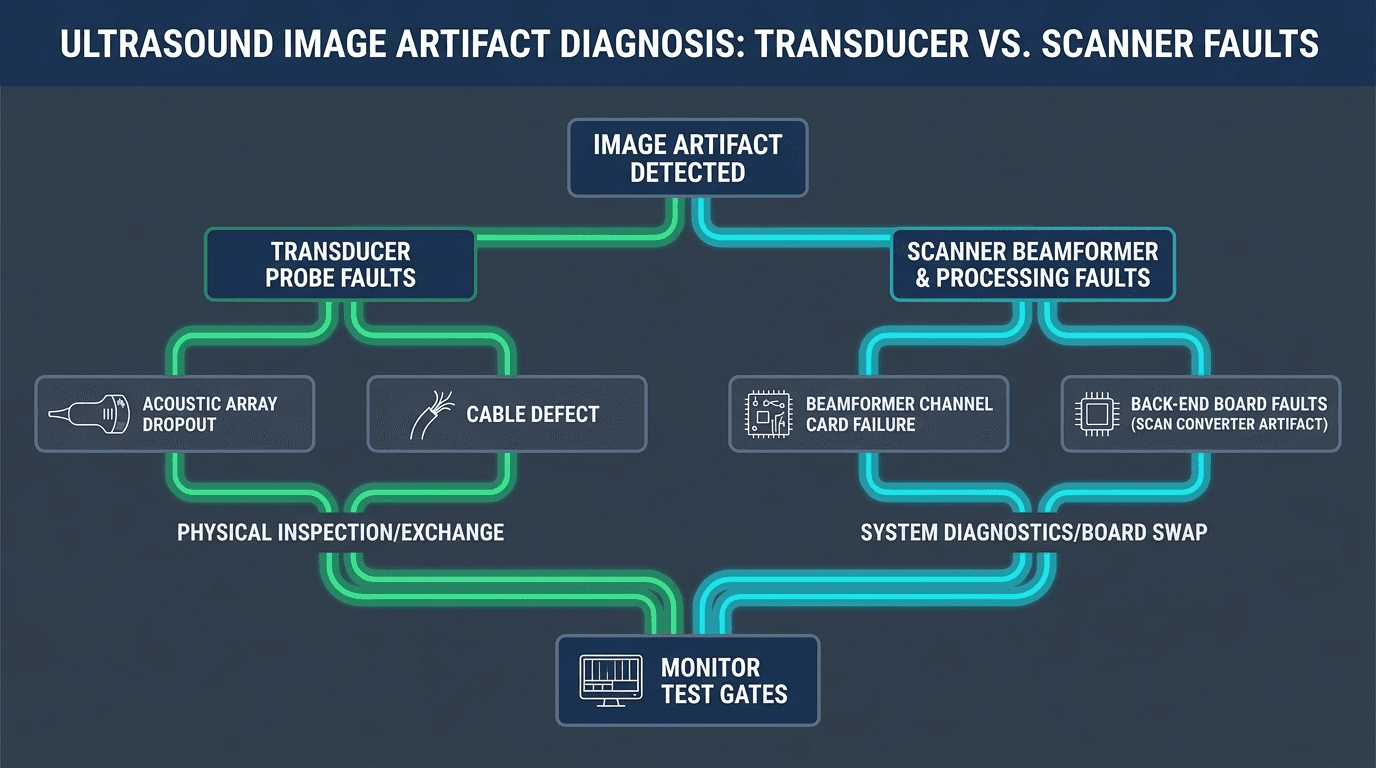
Is this artifact the probe or the scanner? The first three tests that separate them
When a sonographer or clinical department flags an ultrasound system for image degradation—such as a dark vertical line cutting through a fetal profile, grainy blizzard noise across a cardiac chamber, or missing Doppler color flow—the clinical urgency is immediate. In many healthcare facilities, the default reaction is to immediately request a replacement probe or declare the scanner's main processing unit dead. However, because the ultrasound imaging chain is a tightly coupled electro-acoustic pipeline extending from microscopic piezoelectric ceramic elements through high-density micro-coaxial cables, zero-insertion-force (ZIF) connectors, front-end analog beamformers, digital scan converters, and video display controllers, an artifact at the screen can originate at either end of the signal path 1 7.
Making an unverified assumption is costly. Sourcing a replacement transducer when the fault actually lies in a blown transmit/receive (T/R) switch ASIC on the system's front-end board leaves the artifact completely intact while burning thousands of dollars of departmental capital. Conversely, ordering a costly beamformer exchange board when the root cause is a broken micro-coaxial cable strand or delaminated acoustic lens creates unnecessary downtime. To avoid these pitfalls, Healthcare Technology Management (HTM) professionals and service engineers should execute a systematic, 10-to-15-minute bench localization protocol comprising three core non-invasive tests before placing a service order or opening system covers.
- [object Object]
- [object Object]
- [object Object]
BMUS documentation emphasizes that over 90% of transducer-related operational defects can be uncovered through meticulous visual inspection of the housing, strain reliefs, and connector pins combined with this simple in-air reverberation and dropout check 1. Resolving this primary fork allows the service team to route the repair immediately to either component-level probe restoration or console board-level diagnostics.
| Observed Image Artifact | Swap-Test Behavior | Primary Root Cause Subsystem | Actionable Engineering Next Step |
|---|---|---|---|
| Single sharp vertical black line / narrow dropout | Follows probe across all ports; absent with known-good probe | Transducer: Dead PZT element, detached flex bond, or snapped micro-coax wire | Route to probe repair for micro-soldering, flex bonding, or array replacement |
| Wide vertical dark band (8 to 32 contiguous channels) | Persists in exact same screen location across all connected probes | Scanner: Front-End / Beamformer board channel IC or T/R switch ASIC failure | Isolate front-end card slot; inspect beamformer front-end board for component rework or exchange |
| Wide vertical dark band (8 to 32 contiguous channels) | Follows probe; flex movement causes intermittent flicker | Transducer: Broken micro-coaxial cable bundle strand or bent ZIF connector pin | Inspect probe connector pins under magnification; perform cable harness replacement or pin straightening |
| Focal dark wedge / shadow in near field (curved or linear) | Follows probe; physical inspection reveals soft or bubbling lens | Transducer: Acoustic lens delamination, gel ingress, or RTV silicone degradation | Perform acoustic re-lensing and de-bubbling per probe repair vs replace guidelines |
| Universal background snow / hash noise across all depths | Present on all ports and all probes; unaffected by probe disconnection | Scanner: Power supply switching ripple, failed filter caps, or RF ground loop | Check DC power supply rail ripple with oscilloscope; review ultrasound power supply failure path |
| Cine image freeze, pixelation, or coordinate skew (UI text clear) | Present across all probe types; menus and calipers render perfectly | Scanner: Back-End DSP, Scan Converter frame buffer, or GPU memory fault | Isolate scan conversion board; review backend image-processing board failure guide |
| Total image blackout (B-mode raster active, acoustic area dark) | Follows probe | Transducer: Blown high-voltage bias line, severed common ground, or corrupt probe ID EEPROM | Verify probe ID handshake in system diagnostics; route probe for wiring harness and EEPROM rework |
| Full sector blackout / quadrant loss across all probes | Persists across all probe types and all transducer ports | Scanner: Master high-voltage transmit power supply (HV board) or clock distribution failure | Measure ±HV bias rails (+/- 100V); inspect transmitter pulser board and master timing clock |
Source: Rongtao Medical Engineering Diagnostic Framework & BMUS Equipment QA Standards
Vertical lines, dropout and missing sectors — what each pattern points to (and the swap-test that confirms it)
Vertical image dropouts are the single most common visual complaint in clinical ultrasound. However, the physical width, sharpness, and stability of the dropout line provide definitive clues regarding the underlying mechanical or electronic failure mode. Distinguishing between a single-element open circuit, a multi-channel block failure, and an intermittent cable fracture prevents misdiagnosing a probe fault as a console failure 1 8.
When evaluating vertical dropout morphology, classify the visual pattern into three distinct physical categories:
- [object Object]
- [object Object]
- [object Object]
The clinical impact of dropouts depends directly on array geometry and imaging mode. In a linear or phased array used for vascular or cardiac quantification, element dropouts degrade lateral resolution, increase side lobe clutter, and introduce false flow voids in Color Doppler. In convex abdominal arrays, multi-channel dropouts can obscure focal liver lesions or gallstones, leading to severe diagnostic errors. Clinical engineering teams should reference the GE ultrasound board symptom decision path or brand-specific diagnostic paths when system-side beamformer issues are verified.
Noise, sensitivity loss and dark wedges — probe lens/array versus beamformer versus backend versus display
Not all ultrasound image artifacts manifest as clean vertical lines. More complex failure modes involve diffuse background noise, progressive penetration loss, focal near-field dark wedges, or image tearing. Isolating these patterns requires understanding the functional boundaries between the acoustic stack, the analog front-end, digital scan conversion, and power distribution 1 7.
- [object Object]
- [object Object]
- [object Object]
- [object Object]
Physics artifact or equipment fault? Recognizing the patterns you should NOT chase as a hardware defect
A major source of wasted engineering time and unnecessary service dispatches is mistaking fundamental acoustic physics artifacts for hardware malfunctions. Ultrasound imaging relies on simplified physical assumptions: that sound travels in a straight line at exactly 1,540 m/s, that attenuation is uniform, and that echoes originate only from the main beam axis. In living clinical anatomy, these assumptions are routinely violated, producing predictable acoustic artifacts that sonographers learn to interpret but service engineers must recognize to avoid unnecessary hardware replacement 1 6.
| Artifact Classification | Acoustic / Physical Mechanism | How to Prove It Is NOT a Hardware Defect | Operator / Clinical Remedy |
|---|---|---|---|
| Acoustic Shadowing | High acoustic attenuation or reflection from bone, calcifications, or gallstones blocking distal sound | Shadow moves when the probe is angled away from the calcified structure; disappears in homogeneous phantom | Change acoustic window; adjust beam steering angle; reposition patient |
| Posterior Acoustic Enhancement | Sound passes through low-attenuation fluid (cysts, bladder, gallbladder) with less attenuation than adjacent tissue | Enhancement region shifts with cystic structure; uniform response in solid test phantom | Reduce far-field TGC sliders behind fluid-filled structures to normalize brightness |
| Reverberation & Comet-Tail | Sound bouncing back and forth repeatedly between two strong parallel specular reflectors (e.g., biopsy needle, pleural line) | Artifact orientation follows the angle of the reflector; disappears when scanning water or gel block without targets | Change angle of insonation; decrease overall gain; adjust acoustic output power |
| Refraction / Edge Shadowing | Sound beam bending at the curved boundary between tissues with different propagation speeds (Snell's Law) | Thin shadow margins originate only at curved margins of vessels or cysts; absent in flat phantom targets | Utilize spatial compound imaging (e.g., CrossXBeam, SonoCT) to fill in shadow margins |
| Mirror Image Artifact | Sound reflecting off a deep, highly reflective planar interface (diaphragm, pleura) creating false duplicate structure | Duplicate anatomy appears strictly deeper than the reflective boundary; disappears when beam axis is altered | Reposition probe angle so the acoustic beam strikes the boundary non-perpendicularly |
| Spectral / Color Doppler Aliasing | Blood flow velocity exceeds the Nyquist limit (PRF / 2), causing velocity wrap-around and color mosaic | Occurs only at high velocities; flow baseline and PRF controls smoothly unwrap the signal | Increase pulse repetition frequency (scale); shift Doppler baseline; lower transmit frequency |
| Side Lobe & Grating Lobe Clutter | Secondary off-axis acoustic energy beams reflecting from strong off-axis structures into cystic lumens | Artifactual echoes inside fluid disappear when tissue harmonic imaging (THI) is enabled | Activate Tissue Harmonic Imaging (THI); adjust focal zone directly to region of interest |
Source: BMUS Quality Assurance Reference & Clinical Ultrasound Engineering Guidelines
Before escalating any image-quality complaint to component repair, the service engineer should verify that the artifact cannot be eliminated by standard scanning controls: toggling Tissue Harmonic Imaging (THI), enabling spatial compounding (e.g., CrossXBeam / SonoCT), adjusting the focal zone depth, or resetting the user preset to factory default. If an artifact is reproducible only on a specific patient's anatomy but vanishes completely in a standardized phantom or air-reverberation test, the issue is acoustic anatomy, not a defective board or transducer.
What evidence to collect before requesting a probe-repair or board-repair quote
When an equipment fault is definitively established, obtaining an accurate, rapid repair quotation requires providing concrete technical evidence rather than a vague description such as 'image looks bad' or 'probe not working'. Professional repair laboratories require specific data points to triage component-level feasibility, allocate replacement circuit boards, and quote accurate turnaround times 7 8.
- [object Object]
- [object Object]
- [object Object]
- [object Object]
- [object Object]
- [object Object]
Submitting this complete evidence package enables the repair facility to determine whether a probe requires a straightforward acoustic re-lensing, micro-coaxial cable re-termination, or complete array replacement, or whether a scanner requires an exchange beamformer or scan converter board.
When to stop testing and escalate: safety hard-stops and the qualified-service boundary
While in-air reverberation and probe swap tests are safe, routine procedures for clinical engineering staff, certain fault conditions represent non-negotiable safety hard-stops. In these scenarios, testing must cease immediately, the equipment must be quarantined from clinical rotation, and the asset must be routed to a qualified repair facility equipped with certified electrical safety and acoustic measurement instrumentation 2 5.
- [object Object]
- [object Object]
- [object Object]
- [object Object]
Frequently Asked Questions
Does a vertical line on my ultrasound image always mean a dead probe element?
No. While a single-element piezoelectric crystal fracture or broken micro-coaxial wire is the most common cause of a fine vertical dark line, identical vertical dropout lines can be generated by a failed transmit/receive (T/R) switch ASIC on the scanner's beamformer board, a damaged connector pin on the system backplane, or a corrupted channel calibration table. The only way to prove the fault is inside the probe is by performing a cross-port swap or connecting a known-good probe to see if the line disappears on the console 1 6.
If swapping probes makes the artifact disappear, is the scanner definitely fine?
In the vast majority of cases, yes—if the artifact tracks the suspect probe to another port or system and vanishes when a known-good probe is connected, the scanner's imaging pipeline is healthy. However, there is one critical exception: multiplexer pin wear or intermittent port-specific connector degradation. If a specific port on the console has bent internal receptor pins, an artifact may appear only when connecting high-density 192-channel probes while low-density 64-channel probes appear normal. Testing the suspect probe across multiple physical ports eliminates this variable 7.
What is the in-air reverberation (sensitivity) test, and is it a qualified test a biomed can run?
The in-air reverberation test is a standardized, non-invasive frontline quality assurance method endorsed by the British Medical Ultrasound Society (BMUS) and IPEM Report 102. Because the acoustic impedance of air reflects virtually all ultrasound energy back into the transducer, holding an un-gelled probe in air at maximum gain produces a clean, horizontal ringing pattern. Any localized drop in reverberation line depth or vertical gap indicates dead elements or lens delamination. It is a fully qualified Level-1/Level-2 QA procedure that any trained biomedical engineer can perform in under two minutes at the point of care 1.
When is image noise a board fault rather than a probe fault?
Image noise is confirmed as a console board or power supply fault when: (1) the noise (speckling, herringbone patterns, or high-frequency hash) is present across all transducer ports and across multiple different probe models; (2) the noise remains visible on the screen even when all probes are unplugged from the console; or (3) the noise intensifies when peripheral motors, cooling fans, or battery charging circuits engage. In these scenarios, the root cause is typically DC power supply switching ripple, failed electrolytic filter capacitors, or broken chassis RF ground braid 7.
How many dead elements can a probe have before it must be retired instead of repaired?
There is no single universal dropout count that triggers retirement; the decision follows a uniformity rating rather than a fixed number. The AIUM Quality Assurance Manual for Gray Scale Ultrasound Scanners, referenced by the AIUM Transducer Testing statement, uses a simple scale: a uniform array with no dropout is rated 1 and is operating well; one or two minor nonuniformities is rated 2 ('watch and wait') and the probe remains usable with monitoring; three or more minor nonuniformities, or any single major flaw such as a full dead-channel line, is rated 3 — the probe should be removed from diagnostic service and replacement planned, and Doppler beams must not be steered from the dead-element region 2. Because dead elements degrade contrast resolution, can cause artificial cyst filling, and corrupt Doppler spectra, that rating-3 boundary is the practical go/no-go line 1. However, a probe at that boundary does not necessarily require disposal: if the dropout traces to broken micro-coaxial wiring, a cold solder joint, or a detached flex circuit rather than a depoled ceramic array, component-level probe repair can restore full channel functionality at a fraction of OEM replacement cost 3.
Where Rongtao fits—and where it does not
Guangzhou Rongtao Medical Technology Co., Ltd. serves medical equipment distributors, healthcare technology management (HTM) departments, refurbishers, and independent service organizations (ISOs) across more than 140 countries with specialized multi-brand ultrasound repair services and tested replacement parts. Understanding our exact technical capabilities and operational boundaries ensures transparent, reliable service delivery.
- [object Object]
- [object Object]
How to Request a Fast, Accurate Repair or Exchange Quote
To receive an actionable technical evaluation and competitive quote within standard 5–8 business-day repair turnaround, please compile the following information and submit it through our contact and quote request form:
- [object Object]
- [object Object]
- [object Object]