
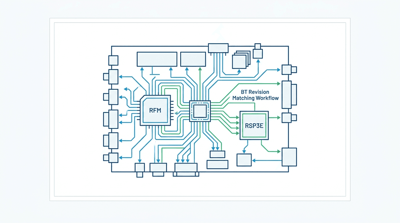
What BT level is my Voluson E8, and why does it decide which board I need?
When servicing a down GE Voluson E8 or E8 Expert, the single most common mistake made by biomedical engineers and clinical service technicians is ordering replacement printed circuit board assemblies (PCBAs) based solely on the scanner model name. Unlike systems with a single static hardware configuration throughout their commercial life, the Voluson E8 platform evolved across more than a decade through distinct development milestones known internally and across the service community as BT levels (short for Break Through) 5.
Introduced originally under FDA 510(k) clearance K061682 in July 2006, the Voluson E8 hardware architecture underwent continuous refinement through the introduction of the E8 Expert (K101236 in 2011), the E8 Expert Limited Edition (K131267 in 2013), and successive digital beamformer iterations up to the final family filing K192159 in 2019 1. A BT level represents both a software feature tier and a synchronized physical hardware revision level. When GE released a new BT generation, changes were frequently introduced across three interdependent sub-systems: the Back-End Processor (BEP) computer architecture, the operating system kernel, and the acoustic front-end / radio-frequency beamformer module (RFM) boards.
This dual nature is clearly documented in official OEM documentation. For example, GE HealthCare's official Service Shop catalog lists the 'Voluson Upgrade E-series BT18 to BT21' (Catalog Item H48711ND) as a comprehensive kit that includes both 'Hardware and Software', migrating the underlying computing engine to a 64-bit Windows 10 version 1809 operating system while updating application modules such as Shadow Reduction, Slowflow3D, and fetalHQ 3. Attempting to install an earlier RFM beamformer or motherboard into a BT18+ machine without matching firmware and hardware revisions can trigger bus synchronization faults, boot loops, or probe communication failures — the exact outcome depends on the boards involved, so treat any cross-generation swap as unverified until part numbers and the software stack are confirmed.
| BT Generation | Approx. Intro Year | Associated FDA 510(k) Milestones | Host / BEP Computer Generation | Key Front-End / Beamformer Architecture | Board Interchangeability & Service Rules |
|---|---|---|---|---|---|
| BT08 / BT09 | 2008–2009 | Original clearance K061682 (2006); no E6/E8/E10 family filings between 2006 and 2011 — early units fall inside this gap | Early BEP architecture; GBE610 motherboard (inventoried as 'Voluson E6(BT09)') and early GEB800 family | Early beamformer and front-end generations — record the exact board family from the card-cage label | Early chassis; do not assume later beamformer compatibility without verifying the BEP, backplane and software stack. |
| BT10 | 2010 | K101236 (2011): introduces E8 Expert and E6 (model family H48681BD/H48681BX/H48681BM) | BEP generation with BT10-tagged mainboard KTI302071-2 (legacy archive); GEB800 family motherboards | RFM201 / RFM221 beamformer generations — revision suffixes must be read from the label | First E8 Expert production baseline; motherboards require exact KTI part-number matching. |
| BT12 / BT13 / BT13.5 | 2012–2013 | K113758 (Jan 2012), K122327 (Sep 2012), K131267 (Jun 2013, adds E8 Expert Limited Edition), K132913 (Nov 2013) — the densest family-filing period | BEP evolution across the Expert generation — verify OS and host level from the unit itself | Refined RFM221 revision series (suffixes -1 through -6 appear across catalog and inventory; their BT attribution is not documented) | BT13.5 appears in dealer tables only — verify from your system; exact revision matching remains the rule. |
| BT14 / BT15 | 2014–2015 | K142472 (Feb 2015), K152567 (Nov 2015) | BT15-tagged BEP kit KTZ303830 and RSP3-3C PSU KTZ303892 in the legacy archive; BT15-era units carry EC300-series software designators | RTF TI board KTZ303955 (catalog tag: E8/E10 BT15) | RTF TI board is BT15-tagged in catalog listings; RSP3E PSU family (KTI303892-12/-16) serves this era onward. |
| BT16 / BT18 | 2016–2018 | K162269 (Oct 2016), K172342 (Sep 2017), K181985 (Nov 2018) | Late-generation BEP host; the BT18-to-BT21 upgrade path migrates to 64-bit Windows 10 (GE kit H48711ND) | RFM323F.P18 beamformer assembly (GE P/N 5729044-7) appears in the verified catalog for the E8 | Verify RFM323F backplane and firmware match before any swap; do not assume earlier-BT chassis host it. |
| BT19 / BT20 / BT21 | 2019–2021+ | K192159 (Aug 2019, last E6/E8/E10 family filing), K201768 (Oct 2020, E10-only) | Windows 10 version 1809 (64-bit) OS via GE H48711ND BT18-to-BT21 upgrade kit | Late RFM generations; a public BT20 service manual documents the late card-cage architecture | BT19 appears in dealer tables only — verify from the system before ordering; expect matched boot ROM and firmware requirements. |
Source: Synthesized from GE HealthCare service documentation, FDA 510(k) filings, SonoMed Services technical guides, dealer service indices, and Rongtao Medical hardware inventory records. Dealer tables disagree on edge generations (BT13.5, BT17, BT19) — verify the level from your own system before ordering parts.
To determine the exact BT level of a suspect Voluson E8 or E8 Expert in the field, technicians should execute the following verification steps before removing cards:
- Software Utility Verification: Power on the system, enter the Utility menu, and navigate to System Setup > Service / System Information. Record the exact Software Version (the EC-series designator — EC300 appears on BT15-era units in the legacy archive), the Application Version, and the BT level explicitly listed on screen.
- Console Serial Plate Check: Inspect the primary rating plate on the rear lower chassis. Record the Model Number (e.g., Voluson E8 or Voluson E8 Expert), Model Code (e.g., H48681BD), and Manufacturing Date.
- BEP Host Label Inspection: Power the system down and disconnect mains, then remove the lower side cover to access the Back-End Processor housing. Record the BEP assembly part number (e.g., KTZ303830) and the installed motherboard designation (e.g., GBE610, GEB800, or KTI301089-7).
- Front-End Card Cage Label Inspection: With the system de-energized, slide out the suspect board (e.g., RFM221 or RSP3E) and document the full GE/Kretztechnik part number including the revision suffix (e.g., KTI303915-1 versus KTI303915-6).
Safety and scope boundary: the steps and isolation protocols in this report assume qualified biomedical or service technicians working on de-energized equipment. Never bypass interlocks, never energize a system with boards removed except under a controlled, qualified test plan, and do not return a repaired system to clinical use without full functional and electrical-safety verification. A given symptom can have several causes — the routing tables below name the likely fault domains, not a remote diagnosis.
No power, power drop on boot or reboot loop: RSP3E supply, power management or motherboard?
Power and startup failures are among the most common service calls on field-deployed Voluson E8 consoles. Because the Voluson E8 combines high-power acoustic transmission for 4D-capable transducers with a high-performance PC host processor and sensitive low-noise analog receive channels, its power distribution architecture is split into multiple cascading stages 6 8.
The primary power sub-system centers on the RSP3E Power Supply Unit (represented in Rongtao's verified catalog under revisions KTI303892-12 and KTI303892-16) 9. Mains AC (100–240V AC, 50/60 Hz) enters through an integrated EMI filtering inlet and power switch module, passing into the RSP3E. The supply converts mains into standby DC power (+5VSB), primary computing DC rails (+3.3V, +5V, +12V, -12V, +24V), and dedicated high-voltage acoustic DC rails (+/- HV) for the front-end pulsers. The RSX Power Management Board acts as the intelligent sequencing watchdog, monitoring rail stability, thermal sensors, and Power-Good handshakes between the BEP host and the acoustic card cage.
| Observed Symptom / Behavior | Initial Indicator & Fan Status | Primary Hardware Domain | Suspect Assembly & Representative P/N | Engineering Test & Safe Isolation Protocol | Documented Fix & Benchmark Turnaround |
|---|---|---|---|---|---|
| Total Inaction (Dead System) | No standby LEDs; cooling fans stationary; no relay click on breaker engage. | Mains Inlet / Primary AC/DC Power Supply | RSP3E Power Supply (KTI303892-12 / KTI303892-16) 9 | Check mains cord, inlet circuit breaker, and internal primary fuses with DMM. Measure +5VSB standby voltage at power distribution harness. | Rebuild RSP3E supply: primary rail capacitors and control IC replaced, then 48-hour real-machine burn-in. Documented in Case 013 (5-day TAT) 9. |
| Power Drop on Boot (Trips after 1–3 sec) | Fans spin briefly; front console LED blinks once; system shuts down immediately. | Secondary DC Overcurrent / Shorted Card in Cage | RFM Beamformer (KTI303915) or RSP3E Secondary Rail | Disconnect all probes. With mains disconnected between steps, extract front-end cards (RFM, RFI, RTF) one by one and re-power after each removal to locate the clamping rail. | Documented on a Voluson E10: main-PSU rail rebuild and capacitor refresh cleared a boot power drop in 5 days (Case 011) 9. On the E8, isolate the current-limited rail by card extraction before condemning the supply or a beamformer. |
| Boot-Time Power-Management Error | System powers on but halts during initialization with power management error on screen. | Power Sequencing & Rail Monitoring | RSX Power Management Board | Monitor Power-Good timing signals on the RSX backplane bus with an oscilloscope; verify rail threshold detection circuits. | RSX rebuild: sequencing IC and rail monitor replaced, power-good signal verified at every boot stage. Documented in Case 012 (6-day TAT) 9. |
| Continuous Auto-Reboot Loop | System starts boot sequence, displays initial splash, resets, and repeats indefinitely. | Hardware Initialization / Corrupt EEPROM | BEP Host Motherboard / Configuration EEPROM | Verify front-end supply voltages during boot; check BEP CMOS battery voltage; inspect BIOS POST debug codes on host mainboard. | Rebuild front-end voltage regulation circuit; reflash configuration EEPROM; 48-hour live chassis soak. Documented in Case 008 (8-day TAT) 9. |
| System Hangs Before Scanning Interface | Power rails remain steady; fans run continuously; boot hangs on Windows or GE splash. | Host BIOS / System Control Board | System / Control Board & GEB800 Motherboard 9 | Check for ESD damage near peripheral ports; verify SATA storage drive health and boot ROM integrity. | System-board ESD-damage repair and boot-ROM reflash, boot sequence verified end to end. Documented in Case 005 (5-day TAT) 9. |
Source: Synthesized from GE technical manuals, MedWrench troubleshooting cases, and Rongtao Medical documented repair case logs
When encountering power anomalies, biomedical engineers should consult our comprehensive ultrasound power-supply failure decision path for generic switching-supply isolation techniques, while applying the specific RSP3E voltage rail thresholds detailed above. For a field example of this fault class, see our documented Voluson E8 no-startup case note.
No echo, phantom probe or dead channels on every probe: RFM family, RFI front-end or probe interface?
Image formation on the Voluson E8 depends on a high-density, multi-channel acoustic signal chain. When clinicians report that the scanner displays a black ultrasound sector ('no echo'), fails to recognize attached transducers ('phantom probe' or 'no probe detected'), or exhibits dark vertical dropouts across multiple probe types, the fault resides within the front-end acoustic card cage 8 11.
The front-end architecture consists of three core assembly tiers:
- Probe Socket Interface & Relay Matrix: The physical cart connector board where probe pins interface with the console. High-voltage reed relays select the active transducer port and route transducer ID lines to the system control bus.
- RFI / RTF Front-End Interface Boards: Including the
RFI21b.P8(P/N KTI302197-6),RFI20C.P8(P/N KTI300614-5), and BT15-eraRTF TI Board(P/N KTZ303955) 9. These boards handle transmit/receive (T/R) switching, initial low-noise pre-amplification, probe temperature sensing, and probe identification decoding. - RFM Beamformer Module Family: The primary digital/analog beamformer cards, including
RFM201.P10(KTI303916-1, -4),RFM221.P10 / RFM221B.P10(KTI303915-1, -4, -5, -6), andRFM323F.P18(5729044-7) 9. These assemblies execute high-voltage pulse generation, dynamic receive focusing delays, Time Gain Compensation (TGC) amplification, and high-speed analog-to-digital conversion (ADC).
| Observed Image / Acoustic Fault | Clinical Presentation | Primary Suspect Subsystem | Representative Part Numbers (Catalog / Inventory) | Gate Test / Differential Diagnosis | Rongtao Documented Case Evidence & Repair Action |
|---|---|---|---|---|---|
| No Echo Signal Across All Probes | 2D screen displays active UI, TGC curves, and depth scale, but ultrasound image area remains completely black or static noise. | RFM Beamformer Channel Stage | RFM221.P10 (KTI303915-1/-6), RFM323F.P18 (5729044-7), RFM423F (KTZ304074-R) | Swap to known-good probe in alternate port. If black screen persists across linear, convex, and phased arrays, probe failure is ruled out; the high-voltage pulser supply or master RFM clock becomes the leading suspect. | Documented no-echo cases: E8 probe-port detection circuit repaired with front-end relay replacement (Case 002, 7-day TAT) and E10 RFM423 channel rework with element-by-element calibration (Case 010, 7-day TAT) 9. |
| Phantom Probe / Port Detection Failure | System reports 'Virtual Probe' or fails to detect probe insertion; cannot switch active transducer ports. | Probe Interface / Front-End Detection Circuit | RFI21b.P8 (KTI302197-6), RTF TI Board (KTZ303955) 9 | Insert probe into Port 1, Port 2, and Port 3. If probe fails in Port 1 but functions in Port 2, an individual connector relay is the prime suspect; if all ports fail, the probe-ID detection circuit on the RFI/RTF board becomes the prime suspect. | Repair probe-port detection circuit and replace defective front-end channel relay. Documented in Case 002 (7-day TAT) 9. |
| Dead Vertical Lines / Channel Dropouts | Consistent vertical black stripes or shadows in 2D image sector, appearing at identical geometric angles across multiple probes. | RFM Beamformer Receive Channel Array | RFM221B.P10 (KTI303915-4/-5), RFM201 (KTI303916-1/-4) 9 | Perform in-air reverberation test and probe-swap test. If vertical line persists across different probes, dead element is ruled out and the beamformer receive channel becomes the prime suspect. | Front-end IC replacement with full channel-map recalibration, documented on a Voluson E10 RFM beamformer (Case 001, 6-day TAT); apply the same channel-isolation logic to the E8's RFM201/RFM221 family 9. |
| Degraded Image Clarity / Low Contrast | Image appears soft, noisy, and lacks penetration across all imaging modes (2D, CFM, PW Doppler). | TX/RX Transmit-Receive Channel Network | TX/RX Board / RFM Transmit Network | Verify high-voltage transmit amplitude on test points with high-voltage probe; calibrate TGC gain response against reference phantom. | TX/RX channel network rework and element-by-element gain recalibration against acoustic phantom. Documented in Case 004 (6-day TAT) 9. |
| Thermal-Dependent Image Anomaly | Scanner operates normally for 15–30 minutes, then develops channel streaks, noise, or freezes once warm. | Beamformer Solder Fatigue / Thermal Degradation | RFM beamformer family (documented on the DBM64 beamformer of a Voluson P8) 9 | Run diagnostic thermal cycling; monitor component temperatures on beamformer ICs with thermal imaging camera during warm-up. | Thermal-cycle isolation with solder-joint reflow on suspect channels and thermal-paste refresh, warm-soak retest. Documented in Case 007 (Voluson P8, 8-day TAT) 9. |
Source: Synthesized from GE Voluson service manuals, doc-market technical cases, and Rongtao Medical documented repair cases
For engineering teams performing acoustic localization, cross-reference this workflow with our specialized guide on ultrasound beamformer front-end board failure and our test protocol for image artifacts: probe vs scanner diagnosis.
Freeze, hang or image-quality loss: motherboard, TX/RX or back-end?
When a Voluson E8 boots successfully and initializes the front-end but subsequently freezes mid-exam, drops frame rates, or exhibits corrupted display output, the failure is situated in the host computing and back-end processing pipeline. The Voluson E8 Back-End Processor (BEP) houses an industrial computer mainboard, multi-channel DSP boards, graphic video cards, and specialized user-interface controllers 6 8.
| Observed Fault | Primary Hardware Assembly | Catalog / Inventory Reference | Underlying Failure Mechanism | Diagnostic & Corrective Protocol |
|---|---|---|---|---|
| Intermittent System Freeze During Scanning | BEP Host Motherboard (GEB800 / GBE610) | KTI301089-7 / KTI301086-4 (GEB800) 9 | BGA solder joint micro-cracking beneath host chipset or power-management regulator IC thermal breakdown. | Run 48-hour continuous load test. Motherboard chipset reflow and power-management IC replacement, stability confirmed under 48-hour real-machine load. Documented in Case 003 (7-day TAT) 9. |
| Display Output Loss with Active Console | 450video Graphics Card / Video Interface | 450video Card SP00884 (Shared E6/E8) 9 | Video GPU failure, EDID handshake corruption, or corrupted display output driver. | Verify video output via external VGA/DVI monitor; replace 450video graphics card or rework video output stage. |
| Unresponsive Touchscreen / Black Touch Panel | Operator Touchscreen Assembly | Touch Screen KTI302969 (Shared E6/E8) 9 | Touch panel digitizer controller IC breakdown, backlight CCFL/LED inverter rail collapse, or worn ribbon harness. | Replace touch controller IC, rebuild backlight power rail, and replace worn internal flex ribbon. Documented in Case 006 (4-day TAT) 9. |
| Rotary Knobs / TGC Sliders Unresponsive | Operator Control Panel Assembly | Control Panel KTZ304229 / 5729168-14, Numeric Keyboard SP00777 9 | Optical rotary encoder wear, TGC potentiometer carbon track degradation, or panel controller USB interface lockup. | Encoder bank replacement, ribbon refit and panel-firmware re-pair. Documented in Case 014 (Voluson S6, 4-day TAT) 9. |
Source: Synthesized from MedWrench engineering discussions, GE service manuals, and Rongtao Medical case studies
For deeper analysis of control console faults, refer to our specialized technical report on ultrasound control panel and touch display failure.
Which E8 boards are shared with the E6 and E10 — and which never swap across generations?
A key advantage of managing a GE ultrasound fleet is platform modularity: several complex assemblies are shared across the Voluson E6, E8, and E10 series. However, assuming universal interchangeability without verifying part numbers and revision suffixes introduces severe operational risks. Installing an E10-specific beamformer into an E8, or mixing early BT09 motherboards into a late-BT chassis, can result in bus contention or non-booting systems 9 10.
| Assembly Name | Part Number / Revision | Voluson E6 | Voluson E8 / E8 Expert | Voluson E10 | Interchangeability Rule & Engineering Boundary |
|---|---|---|---|---|---|
| RSP3E Power Supply Unit | KTI303892-12 / KTI303892-16 | No (Uses RSP2f KTI302752) | Yes (Standard PSU) | Yes (Standard PSU) | Shared across E8 and E10. Catalog lists both revisions for 'VOLUSON E8 10'; still match the revision suffix on the label — the functional delta between -12 and -16 is not publicly documented. |
| Operator Control Panel (White-New) | KTZ304229 / 5729168-14 | No (Model-specific) | Yes | Yes | Shared across E8 and E10. Catalog tag: VOLUSON E8 E10; verify revision and console trim at quote. |
| Numeric Keyboard Assembly | SP00777 (White Panel) | No | Yes | Yes | Shared across E8 and E10. Catalog tag: E8 E10; verify panel trim at quote. |
| RTF TI Front-End Board | KTZ303955 (BT15) | No | Yes (BT15 only) | Yes (BT15 only) | Shared across E8 and E10 at BT15. Catalog tag: VOLUSON E8 E10(BT15); requires its matching BT15-era platform software. |
| 450video Graphics Card | SP00884 | Yes | Yes | No (Model-specific GPU) | Shared across E6 and E8. Catalog tag: VOLUSON E6 E8 — match by label. |
| Operator Touch Screen | KTI302969 | Yes | Yes | No (Model-specific display) | Shared across E6 and E8. Catalog tag: VOLUSON E8 E6 — match by label. |
| GEB800 Host Motherboard | KTI301089-7 / KTI301086-4 | Yes | Yes | No (Uses GEB3110 5747700-6) | Shared across E6 and E8. Inventory tag: Voluson E6/E8; match BIOS/firmware to the system's BT tier and verify before swapping. |
| GBE610 Host Motherboard | KTI300744-2 / KTI301087-2 | Yes (BT09-tagged) | No | No | Dedicated to Voluson E6(BT09) — an early-E6 motherboard in live inventory; not an E8 part. |
| RFM221 Beamformer Assembly | KTI303915-1, -4, -5, -6 | No (E6 uses its own beamformer lines — verify by part number) | Yes (E8-dedicated) | No (Uses RFM423F KTZ304074-R/5729200-8 or RFM323H.P20 KTZ304141/5809347-5) | Dedicated to Voluson E8. Inventory carries four revision variants tagged Voluson E8; the suffix denotes the engineering-change level — match the exact one on the installed label. |
| RFM423F Beamformer Assembly | KTZ304074-R / 5729200-8 | No | No | Yes | Dedicated to Voluson E10 (inventory tag: VOLUSON E10); not an E8 part. |
Source: Synthesized from Rongtao Medical verified catalog rows, live inventory records, and OEM service cross-references
In multi-brand ultrasound servicing, assuming that boards with similar physical form factors can be swapped freely across BT generations is the fastest route to corrupted system presets and damaged pulser stages. On the Voluson E8 platform, matching the exact part number and revision suffix from the PCB label is a mandatory service boundary.— Rongtao Medical Ultrasound Hardware Diagnosis Center
How do I verify the RFM221 or RSP3E part number and revision before ordering a repaired or tested board?
Before ordering a replacement board or sending a defective module for component-level repair, biomedical engineering teams must extract and verify the complete alphanumeric label affixed to the printed circuit board. GE Healthcare and Kretztechnik assemblies feature multi-layer identification labels that communicate critical revision history 9.
| Label Field / Component | Example Marking | Functional Meaning | Service & Procurement Implication |
|---|---|---|---|
| Primary Model / Board Name | RFM221.P10 or RSP3E | Proprietary board family and fundamental circuit design designation. | Identifies the subsystem domain; insufficient on its own to place a purchase order. |
| Manufacturer Part Number (P/N) | KTI303915 or 5729044 | Base catalog identifier assigned by GE / Kretztechnik engineering. | Defines the broad hardware platform generation. |
| Revision Suffix (Dash Number) | -1, -4, -5, -6, -12, -16 | Engineering-change level of the board design. GE does not publicly document the functional delta between suffixes. | Critical matching parameter. Never substitute one suffix for another (e.g., RFM221 KTI303915-1 versus -6, RSP3E KTI303892-12 versus -16) without supplier confirmation. |
| Serial Number & Date Code | SN: 24891 / DOM: 2015-08 | Unique manufacturing unit identifier and build date. | Used for batch tracking, warranty registration, and service history. |
Source: Compiled from Rongtao Medical technical quality verification procedures and physical board inspection records
Once a repaired or tested exchange board is received, rigorous incoming quality inspection is essential before returning the ultrasound system to patient care. Technicians should execute the structured protocol outlined in our board part-number verification and acceptance guide, encompassing:
- Physical Inspection: Verify conformal coating integrity, inspect gold finger card-edge connectors for oxidation or mechanical wear, and confirm no cracked SMD capacitors or overheated PCB traces.
- Static Impedance & Diode Checks: Measure resistance across primary DC power rails (+3.3V, +5V, +12V, +/- HV) relative to ground prior to card cage insertion to verify no shorted rail protection diodes.
- Live Chassis Burn-In Validation: Install the board into a verified Voluson chassis; verify error-free BIOS POST, complete automated diagnostic self-tests (Diagnostics Menu), and run continuous 48-hour scanning load tests across convex, linear, and 4D probes.
What does the FDA record show for the Voluson E8 family — clearances, recalls and known issues?
Understanding the regulatory history of the Voluson E8 family provides objective context on platform longevity, software updates, and documented field safety notices. An analysis of the U.S. FDA 510(k) premarket notification database and device recall records illustrates the platform's regulatory lifespan 1 2.
| 510(k) Number | Decision Date | Applicant / Manufacturer | Device Clearance Name | Platform Regulatory Significance |
|---|---|---|---|---|
| K061682 | 2006-07-12 | General Electric Co. (Kretztechnik) | GE Voluson E8 Ultrasound System | Initial commercial 510(k) clearance establishing the Voluson E8 platform. |
| K101236 | 2011-02-08 | GE Healthcare | Voluson E6/E8/E8 Expert Diagnostic Ultrasound System (Models H48681BD/H48681BX/H48681BM) | Introduction of Voluson E8 Expert and Voluson E6 under a unified family clearance. |
| K112213 | 2011-09-01 | GE Healthcare | Voluson E6, E8, E8 Expert, E10 Diagnostic Ultrasound System | First family filing to list the Voluson E10 alongside E6 and E8. |
| K113758 | 2012-01-10 | GE Healthcare | Voluson E6/E8/E8 Expert/E10 | Family feature update across all four models. |
| K122327 | 2012-09-21 | GE Healthcare | Voluson E6/E8/E8 Expert/E10 | Family feature update across all four models. |
| K131267 | 2013-06-19 | GE Healthcare | Voluson E6/E8/E8 Expert/E8 Expert Limited Edition/E10 | Addition of the E8 Expert Limited Edition to the family list. |
| K132913 | 2013-11-08 | GE Healthcare | Voluson E6/E8/E8 Expert/E8 Expert Limited Edition/E10 | Family filing retaining the Limited Edition in scope. |
| K142472 | 2015-02-10 | GE Healthcare | Voluson E6 / Voluson E8 / Voluson E10 Diagnostic Ultrasound Systems | Family feature update (E8 Expert variants no longer named in the device list). |
| K152567 | 2015-11-06 | GE Healthcare | Voluson E6, Voluson E8, Voluson E10 Diagnostic Ultrasound System | Family feature update across the three models. |
| K162269 | 2016-10-03 | GE Healthcare | Voluson E6, Voluson E8, Voluson E10 | Family feature update across the three models. |
| K172342 | 2017-09-29 | GE Healthcare | Voluson E6, Voluson E8, Voluson E10 | Family feature update across the three models. |
| K181985 | 2018-11-15 | GE Healthcare | Voluson E6, Voluson E8, Voluson E10 | Family feature update across the three models. |
| K192159 | 2019-08-29 | GE Healthcare | Voluson E6, Voluson E8, Voluson E10 | Final family filing naming the E6/E8/E10 — the last regulatory submission covering the Voluson E8. |
| K201768 | 2020-10-22 | GE Healthcare | Voluson E10 | Voluson E10-only filing, marking the regulatory transition away from new E8 submissions. |
Source: Compiled from U.S. FDA 510(k) Premarket Notification Database via local openFDA extract (14 verified records)
Note that 510(k) device names carry no BT-level information: the clearance cadence bounds the platform's regulatory lifespan (2006 to 2019/2020) but cannot be mapped one-to-one onto BT generations. Where this report pairs a K-number with a BT tier in Table 1, the pairing is an approximate chronological alignment drawn from dealer documentation and Rongtao part records — the authoritative BT level is always the one displayed by your system.
In addition to premarket clearances, the FDA device recall database records 6 recall rows naming Voluson systems — spanning Voluson 730-generation and E-series entries 2. The E8-specific rows are software measurement corrections: M-Mode dimension inaccuracies when pan-zoom is activated, and Pulsed Wave Doppler angle-correction values being disregarded when a spectrum is reloaded or sent to a DICOM station, both at software release 6.x; a further row covers an incorrect operating procedure at software 9.0.x on the E6/E8. A 2012 enforcement report (20120713) documents a family correction across the E6/E8/E8 Expert/E10 line, and in December 2023 an enforcement report (20231222) covered the IC9-RS intracavitary probe (Model J48691PJ) used on Voluson systems 2.
Regulatory & Methodological Notice: Recall numbers and database listings reflect manufacturer reporting actions, regulatory scope, and field corrections. They do not measure failure rates, product incidence, or comparative safety against other OEM brands. A search of the FDA MAUDE database shows that adverse event reports naming the Voluson family remain sparse — single-digit annual counts against over 1,100 general ultrasound reports in 2019. Under passive surveillance with no install-base denominator, that sparsity does not by itself indicate anything about reliability or safety in either direction.
Repair, tested replacement or whole-system upgrade: economic & lifecycle decision framework
When a Voluson E8 or E8 Expert experiences a board failure, healthcare technology managers (HTMs) and clinical engineering leaders face a three-way lifecycle decision: (1) contract for component-level board repair, (2) purchase a verified tested replacement/exchange assembly, or (3) decommission the scanner in favor of a new platform 9. Note that the E8 is not orphaned legacy: GE HealthCare still lists the Voluson E8 in its product portfolio 4 and sells BT18-to-BT21 upgrade kits through its service shop 3.
| Service / Sourcing Route | Typical Turnaround (TAT) | Cost Position (Confirm at Quote) | Technical & Operational Advantages | Primary Risks & Limitations | Recommended Clinical Application |
|---|---|---|---|---|---|
| Component-Level Board Repair | 5–8 business days (typical) 9 | Typically the lowest-cost route — quoted per board | Preserves original system calibration and firmware matching; repairs the specific failed components; backed by 48-hour live-system burn-in. | Requires qualified micro-soldering and real-machine testing capabilities; defective board must be physically shipped for service. | Best for non-critical downtime: Hospitals with backup scanners, ISO inventory replenishment, and cost-conscious clinics. |
| Verified Tested Replacement / Exchange | Depends on matched stock — confirm availability at quote | Typically between component repair and new-assembly purchase — quoted per board | Fastest downtime recovery where a matched, tested board is in stock; 90-day warranty (typical) 9. | Requires exact matching of part number and revision suffix; dependent on supplier stock availability. | Best for urgent clinical downtime: Single-system OB/GYN practices and emergency department ultrasound units. |
| Whole-System Capital Upgrade (e.g. Voluson E10/Expert 22) | Extended procurement, installation and validation cycle | Substantially above board-level repair once probes, installation and staff retraining are included | Access to next-generation matrix probe technology, AI workflow tools, and current OEM service contract coverage. | High capital expenditure; staff re-training required; existing E8 probes may require expensive replacement. | Best for end-of-lifecycle fleets: Facilities requiring high-end fetal echocardiography research or replacing 15+ year old BT08-era units. |
Source: Compiled from Rongtao Medical service standards (typical turnaround, warranty and 48-hour real-machine testing); cost position and dispatch times depend on the specific board and must be confirmed at quote
For engineering teams evaluating broader fleet economics, consult our in-depth guide on ultrasound board repair vs replacement.
Where Rongtao fits—and where it does not
Rongtao Medical operates as an independent multi-brand ultrasound technical repair center and parts supplier. To maintain transparent, professional relationships with clinical engineering teams, ISOs, and distributors, we clearly define our operational scope:
| Operational Domain | Where Rongtao Medical Fits (Capabilities) | Where Rongtao Medical Does Not Fit (Boundaries) |
|---|---|---|
| Board & Assembly Repair | Component-level micro-soldering, IC replacement, power supply rebuilds (RSP3E), chipset reflow, and channel recalibration for Voluson E6, E8, E8 Expert, E10, and Voluson S-series platforms with typical 5–8 business-day turnaround 9. | We do not perform field repairs on energized equipment at customer sites; all board services occur in our static-controlled technical laboratory. |
| Parts Supply & Live Inventory | Verified tested stock of GE Voluson boards (RFM221, RFM201, RSP3E, GEB800, 450video), probe interface cards, power supplies, and control panels with verified photographs and typically 90-day warranty coverage 9. | We do not sell unverified 'as-is' salvage pulls or broker phantom inventory without physical laboratory testing. |
| System Validation & Quality Testing | Every repaired board undergoes 48-hour real-machine testing inside an actual ultrasound system before release, with photo and video evidence supplied where applicable 9. | We are not GE HealthCare's authorized factory representative. OEM names and model designations identify supported equipment only. |
| Software & Licensing | Assistance with hardware-level configuration EEPROM flashing, boot ROM recovery, and hardware diagnostic log interpretation. | We do not bypass, crack, or distribute proprietary OEM application software licenses or unauthorized software keys. |
Source: Rongtao Medical operational service standards and quality assurance protocols
Frequently Asked Questions (FAQ)
Are GE Voluson E8 boards still repairable at the component level?
Documented Rongtao cases cover RSP3E power-supply collapse, probe-interface and front-end faults, TX/RX and beamformer-family channel faults, motherboard faults and touch-panel faults on the Voluson E8 family, each restored at the component level 9. Whether a specific board is repairable depends on the fault and board condition — request a diagnosis before deciding. Component-level repair typically costs well below a new OEM assembly; the exact figure is confirmed per case at quote.
Can I upgrade my Voluson E8 from BT12 or BT13 to BT16 simply by swapping the beamformer board?
No. BT upgrades are coordinated hardware-plus-software packages — GE's own BT18-to-BT21 kit (H48711ND) ships hardware and software together with a new 64-bit Windows 10 1809 operating system 3. Installing an RFM323F beamformer into an earlier-generation chassis can produce bus communication failures and boot-time errors unless the BEP host computer and the full software stack are upgraded at the same time.
Is the Voluson E8 Expert the same platform as the standard Voluson E8 for board replacement?
Yes, with specific generation boundaries. Introduced under FDA clearance K101236 in 2011, the E8 Expert shares the family platform with the standard E8 1 — the RSP3E power supply and shared E8/E10 assemblies apply to both. Later-BT units carry generation-specific front-end cards (the RTF TI board KTZ303955 is catalog-tagged E8/E10 BT15) 9. Always match the exact part number and revision suffix from the installed board label.
What is the typical turnaround time and warranty for Voluson E8 board repairs?
Standard component-level board repairs at Rongtao Medical are completed within a typical turnaround of 5–8 business days 9. Repaired boards and tested replacement stock carry a typically 90-day warranty, backed by 48-hour live-system validation on dedicated Voluson chassis before shipment.
What information should I provide when requesting a Voluson E8 board repair or replacement quote?
To avoid revision mismatches, provide: (1) System model (e.g., Voluson E8 or E8 Expert), (2) BT level / Software Version from the System Info screen, (3) Complete Part Number and Revision Suffix from the board label (e.g., KTI303915-6 or KTI303892-16), (4) High-resolution photos of front and back labels, and (5) Specific symptom description or error codes.
Quote-Ready Evidence Pack: Service Request Handoff
To expedite diagnostic evaluation and obtain an accurate repair or tested-replacement quotation, biomedical engineers and ISO procurement managers should prepare the following structured data package before initiating contact:
| Required Data Item | Location / Source | Example Value | Operational Purpose |
|---|---|---|---|
| Scanner Model & Tier | Console front bezel / rating plate | GE Voluson E8 Expert (Model H48681BD) | Establishes base platform architecture. |
| Software Version / BT Level | Utility > System Setup > System Info | Software EC300 / BT15 | Determines BEP and FPGA firmware compatibility. |
| Board Name & Function | Card cage slot designation / PCB silkscreen | RFM221.P10 Beamformer or RSP3E PSU | Identifies primary subsystem failure domain. |
| Part Number with Revision | Barcode label on component side of PCB | P/N: KTI303915-6 (or KTI303892-16) | Guarantees 100% hardware revision alignment. |
| Board Photographic Evidence | Digital camera / smartphone photos | Clear photos of entire board (front & back) + close-up of labels | Allows engineers to inspect component revisions and check for prior rework. |
| Detailed Fault Description | Clinical observation / service log export | No echo across all probe ports; 2D UI active; boot-time error text if displayed | Directs laboratory bench testing to exact failing circuit stages. |
| Service Request Type & Logistics | Procurement / clinical timeline | Component-Level Repair (5-8 days) vs Tested Exchange Stock; Destination: Munich, Germany | Enables instant routing to our repair lab or immediate parts dispatch team. |
Source: Rongtao Medical Service Intake & Parts Verification Standard
Ready to initiate a diagnostic review or request tested Voluson E8 replacement assemblies? Submit your technical data package through our direct quote flow:
- Submit a technical inquiry and board photos via our Rongtao Medical Technical Contact Portal.
- Browse our verified inventory of GE assemblies on the GE ultrasound parts & board repair catalog.
- Review our multi-brand repair intake standards in our board-repair RFQ template and GE board symptoms decision path.
- For urgent transducer repairs or acoustic lens replacements, consult our dedicated ultrasound probe repair service.