
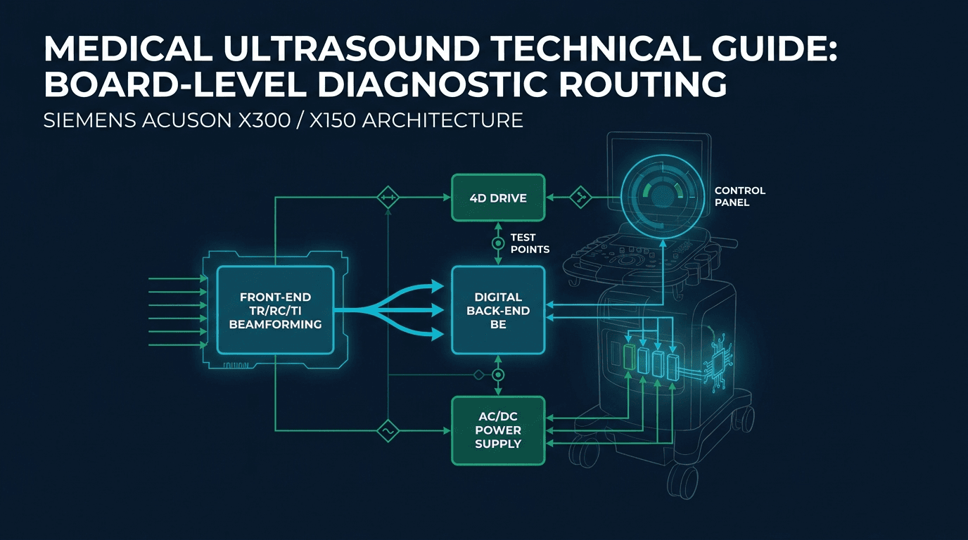
Which ACUSON X-family board domain does my symptom point to?
The Siemens ACUSON X-family — encompassing the ACUSON X300, ACUSON X300 Premium Edition (PE), SONOVISTA X300, and ACUSON X150 — is a widely deployed mid-range shared-service ultrasound architecture. Engineered for cardiovascular, OB/GYN, general imaging, and small-parts examinations, the X-platform utilizes a modular card-cage chassis combined with a dedicated lower power supply module and an upper operator console 1 6.
When an X-family console malfunctions, clinical engineers often encounter confusing symptom presentations because digital back-end logic, acoustic front-end beamforming, and power distribution subsystems are tightly coupled across the chassis backplane. To isolate faults efficiently without swapping unnecessary assemblies, service teams must classify the observed failure into one of four primary hardware domains:
- Acoustic Front-End Domain (TI / TR / RC / CW): Manages transducer multiplexing, high-voltage transmit pulse generation, acoustic beam steering, dynamic receive focusing, and analog-to-digital conversion. Faults in this domain manifest as image-area flicker, vertical black bands (channel dropouts), total echo loss on all probes, or Doppler RF distortion.
- Digital Back-End Processing Domain (BE / IO): Manages digital signal processing (DSP), cine memory buffers, scan conversion, host PC execution, DICOM networking, and video output driving. Faults manifest as operating system freezes, boot loops, communication bus errors, or corrupted display overlays.
- Power Conversion & Distribution Domain (AC Mains / DC-to-DC): Transforms mains AC electricity (100–240 VAC) into regulated low-voltage digital rails (+3.3V, +5V, ±12V) and high-voltage programmable analog transmit rails (±HV). Faults manifest as complete no-power states, immediate circuit breaker trips, over-current shutdowns ('auto shutdown to prevent damage'), or high-frequency ripple interference lines.
- User Interface & 4D Drive Domain (Control Panel / 4D Motor Board): Handles keyboard matrix scanning, rotary encoders, trackball optical sensors, and mechanical drive signals for motorized 4D volume probes (such as the C7F2). Faults manifest as frozen controls, unresponsive buttons, motor stall errors, or extremely prolonged system boot times.
The following diagnostic matrix maps common field symptoms to their primary suspect board domains, candidate part numbers verified in the Siemens ACUSON X300 parts catalog, key differential gating checks, and secondary root causes 4 5.
| Observed Console Symptom | Primary Suspect Domain | Key Candidate Boards & Part Numbers | Differential Gating Step | Secondary Root Cause |
|---|---|---|---|---|
| System displays 'auto shutdown to prevent damage' and powers off | Power Distribution / Over-Current Protection (OCP) | DC Power Supply (10010040 / 10348509 / 10787354), AC Supply (10132402), TR Board (10348311) | Check if V5Ms TEE probe is connected on X300 PE (software 5.0.00/5.0.01 recall check); isolate shorted TR/TI boards | Short circuit on high-voltage pulser rail or clogged cooling fan intake |
| System startup stretched from ~3 minutes to over 10 minutes (boots normally eventually) | User Interface / Serial Bus | Control Panel Assembly (10348373), IO Board (10131806 / 10349046), BE Board (10131990) | Disconnect control panel USB/serial interface cable and boot with external USB mouse; check boot timing | Back-End hard disk drive sector degradation or corrupted host OS log files |
| Severe interference lines / snow across active image on ALL connected transducers | Shared Signal Path: TI / DC Power / TR | TI Board (10566248 / 10131971 / 10348303), DC Power Supply (10010040 / 10348509), TR Board (10348311) | Test in different room/circuit to rule out external EMI; substitution-test DC supply and TR board — in the documented case both were excluded and the TI board was the fault | Failed filter capacitors on DC power supply, external electrical noise, or degraded TI probe-switching circuitry |
| Flicker confined strictly inside ultrasound scan sector; surrounding UI and menus perfectly stable | Transducer Interface (TI) / Probe Socket | TI Board (X300: 10566248 / 10131971; X150: 10132867), Probe Multiplexer | Execute probe-swap gate; press probe lens against gel phantom to confirm transmit/receive response; listen to each probe in turn for intermittent working sound | Defective probe connector pins, micro-relay contact bounce on TI board, or the DC power module that supplies probe operating voltage through the TI board |
| Vertical black bands / missing scan lines at fixed lateral sector positions on all probes | Receive Controller / Front-End Beamformer | RC Board (10010907 / 10131803 / 10427726 / 10348315), TR Board (10348311) | Perform air-scan transducer test with maximum acoustic gain; swap probe to alternate active port | Cracked piezoelectric crystal element in single transducer (if on one probe only) |
| 4D volume acquisition fails, freezes, or generates motor drive error dialogs | 4D Motor Controller / Transducer Mechanism | 4D Motor Board (10348307 / 10348440), C7F2 Transducer Assembly, Back-End BE (10786512) | Test 2D imaging on standard convex probe; if 2D is healthy, isolate 4D board drive signals vs C7F2 motor | Damaged motor drive gearbox inside C7F2 probe or broken 4D cable wires |
| Completely dead console (no cooling fans, no LEDs, no power-switch response) | AC Mains Power Supply | AC Power Supply (X300: 10132402; X150: 10349228), Rear Breaker Switch | Measure AC line voltage at input terminal; inspect rear fuse holder and AC power switch harness | Defective AC front power push-button switch or blown internal varistor |
| Continuous boot loop / hangs indefinitely at Siemens ACUSON splash screen | Digital Back-End Processing / Host PC | Back-End BE Board (10131990 / 10348317 / 10786512), IO Board (10131806) | Inspect BE status diagnostic LEDs on rear card edge; verify SATA hard drive spin-up | Corrupted system operating software or failed memory DIMM module |
| Color Doppler snow / Pulsed-Wave (PW) Doppler spectral baseline noise / audio whine | Back-End Demodulation / Channel Processing | CW Doppler Board (10348502), RC Board (10010907), BE Board (10786512) | Verify B-mode image clarity; if 2D is clean but Color/PW Doppler fails, isolate Doppler baseband circuitry | External RF interference from electrocautery or failing ground reference |
Source: Rongtao Medical Technical Service Archive & Parts Inventory Records (2026)
For broader diagnostic comparisons across Siemens platforms, review our brand-level Siemens board decision path and the ACUSON S2000/S3000 board decision path 5.
No power or 'auto shutdown to prevent damage': power chain first — then the 2009 recall rule-out
In clinical engineering forums, technical discussion boards, and video repair case studies, the single most searched technical failure on the Siemens ACUSON X300 is the abrupt shutdown accompanying the on-screen warning: 'Auto shutdown to prevent damage' 6. When this alert appears, the console immediately cuts DC bus voltages to protect sensitive front-end analog circuitry from catastrophic thermal or over-current damage.
Field service engineers routinely assume that an over-current shutdown is caused by an internal failure within the AC Mains Power Supply (P/N 10132402) or the DC Power Supply module (P/N 10010040 / 10348509 / 10787354 / 10429578) 4. While a degraded DC-DC converter or shorted tantalum bypass capacitor on the backplane can trigger over-current protection (OCP), clinical engineers must first execute a crucial regulatory and software rule-out gate before ordering replacement power modules.
The 2009 FDA Recall Condition Trap:
Official FDA Medical Device Recall records document a critical safety correction (initiated July 24, 2009) covering ACUSON X300 Premium Edition systems running system software versions 5.0.00 and 5.0.01 (model numbers 10348531, 10348532, and 10348533) 2. The FDA record states the condition plainly: when the 64-channel system's V5Ms transesophageal echocardiography (TEE) transducer is used in 128-channel mode, an over-current fault occurs which shuts the system down. FDA lists the root cause as software design, not a failed power module — but at the bedside the behavior is indistinguishable from a catastrophic power-supply breakdown 2.
If your facility services an X300 Premium Edition experiencing automatic shutdowns, verify the installed software version and probe configuration immediately. If the shutdown occurs exclusively when the V5Ms transducer is activated, the root cause is a software/configuration condition rather than a defective hardware power module.
To systematically isolate an over-current shutdown or complete no-power failure on an ACUSON X300 or X150 console, follow this four-stage verification protocol:
- Stage 1 (Mains & Primary Circuit Breaker Verification): Verify that the wall outlet provides stable 100–240 VAC under load. Check the primary circuit breaker and AC input fuses on the rear chassis panel. Measure the output of the AC power supply (X300: 10132402; X150: 10349228). If the AC supply provides stable DC bus voltage to the power bay, the AC front-end is healthy.
- Stage 2 (Transducer & Peripheral Disconnection): Completely power off the console. Disconnect all ultrasound transducers from the TI board ports, and remove all external USB peripherals, video printers, and network cables. Power on the bare chassis. If the console boots without triggering the 'auto shutdown' message, reconnect probes one by one to isolate a defective transducer assembly or the 2009 V5Ms configuration condition.
- Stage 3 (DC-to-DC Rail Measurement — Qualified Personnel Only): If the shutdown persists with zero probes connected, qualified service engineers should measure the low-voltage DC rails (+3.3V, +5V, ±12V) and high-voltage rails (±HV) at the DC distribution test points. A collapsed rail indicates a dead DC power supply (10010040 / 10348509) or a shorted load on the backplane bus. For general power supply troubleshooting frameworks, consult our guide to ultrasound power-supply failure, boot-loop, and shutdown diagnosis.
- Stage 4 (Front-End & Back-End Card Isolation): With the console disconnected from mains power, systematically remove the Transmit (TR) board (10348311), Transducer Interface (TI) board (10566248), and 4D Motor board (10348307). Power on the system. If the OCP trip clears after extracting the TR board, the fault is isolated to the TR card; a shorted high-voltage MOSFET pulser is the common mechanism, but confirm it at component level before condemning the board.
Boot hangs or ten-minute boots: back-end, software load or control panel? A documented case
A second major category of failure on the ACUSON X-family involves system startup anomalies: either the console hangs indefinitely on the Siemens splash screen, or the boot sequence stretches from the normal ~3 minutes to more than 10 to 15 minutes before the imaging software finally loads 5 6.
When faced with extended boot delays, field engineers almost universally condemn the Back-End (BE) processing board (P/N 10131990 / 10348317 / 10786512) or assume that the internal SATA hard disk drive has accumulated bad sectors and requires re-imaging 4. However, documented engineering cases from Rongtao Medical's service archive illustrate an unexpected and highly instructive hardware pathway 5.
Documented Rongtao Service Case Analysis (X300 Prolonged Boot Time):
An ACUSON X300 ultrasound system presented with severely degraded startup performance: the boot process stretched from the normal ~3-minute duration to more than 10 minutes before reaching the clinical scanning interface, with the additional time spent waiting at the 'Checking system configurations' stage. Once fully booted, the system appeared to operate normally, but the extreme startup latency disrupted clinic scheduling. After other fault domains were eliminated, systematic sub-assembly substitution isolated the fault to the control panel circuit-board module — the record attributes the extended self-test to that module's slow response. Replacing the control panel restored the boot time to a stable ~3 minutes, confirmed across repeated boot-cycle retesting, with no back-end BE board modification required.— Rongtao Medical Service Archive Case Record (ACUSON X300 Startup Maintenance Analysis)
The control panel assembly for the X300 is documented in Rongtao's legacy parts registry as P/N 10348373 5; the case record itself names the module, not the part number, so confirm the number on the physical label before ordering. Why does a defective control panel cause a 10-minute boot delay rather than an obvious keyboard error? In the ACUSON X300 architecture, the control panel communicates with the back-end host controller over a dedicated polling bus, and the documented case shows the boot stalling specifically at the 'Checking system configurations' stage. When the panel's interface electronics degrade, the system controller's polling of rotary encoders, trackball sensors, and TGC slider banks does not complete cleanly, so the startup sequence waits and retries before continuing. The failure is silent — the panel can still respond once the system is up — which is exactly why the back-end board and hard drive are so often condemned first.
To isolate boot delays on an X300 or X150 system, use the following three-gate procedure:
- Gate 1 (Control Panel Bypass Test): Disconnect the internal control panel interface harness from the IO/BE board. Connect a standard external USB keyboard and mouse to the rear IO panel. Power on the console. If the boot time drops from >10 minutes back to ~3 minutes, the fault is isolated to the Control Panel assembly (10348373). For additional control-panel troubleshooting, consult our guide to ultrasound control panel, touch screen, and display failures.
- Gate 2 (Hard Disk & Software File Integrity): If the boot hang persists with the control panel disconnected, inspect the mechanical SATA hard drive. Connect the drive to a diagnostic workstation to review S.M.A.R.T. health logs for reallocated sectors. If drive hardware is healthy, perform a clean software restoration using the facility's authorized software media.
- Gate 3 (Back-End BE Board Isolation): If drive sectors and control interfaces are verified, the fault lies within the Back-End (BE) processing board (10131990 / 10348317 / 10786512). Onboard memory bus faults, failed PCI bridge controllers, or degraded power-rail filtering on the BE board require component-level micro-soldering or board replacement.
Interference or flicker on all probes: the documented case that exonerated the DC supply and TR board
Another signature failure mode encountered on mature ACUSON X300 consoles is full-screen acoustic interference that appears across every connected transducer. The console boots into the application software without error codes, but when scanning in 2D or Color Doppler mode, the ultrasound image is overlaid with intense snow, horizontal raster lines, or vertical noise bars 5.
Because the noise appears on multiple probes (convex, linear, phased-array) across all probe sockets, field engineers often struggle to determine whether the fault resides in the incoming mains power, the DC power supply, the Transmit (TR) board, or the Receive Controller (RC) cards 5.
Documented Rongtao Service Case Analysis (X300 All-Probe Image Interference):
An ACUSON X300 ultrasound system initialized normally through boot, but upon entering scanning mode, all connected transducers exhibited severe image interference across the entire active sector. The initial failure analysis followed the conventional hypothesis: global interference affecting all transducers simultaneously originates from either the power-supply conversion section or the front-end acoustic channel boards. Substitution testing replaced the DC main power supply and the Transmit (TR) board — the interference remained completely unchanged, so both were excluded. The analysis then moved to the stages every probe shares: the RC receive-control board and the TI transducer-interface board, which handles the connection and switching of all probe sockets. Replacing the Transducer Interface (TI) board eliminated the interference fault, restoring clean imaging across all transducer ports.— Rongtao Medical Service Archive Case Record (ACUSON X300 Image Interference Maintenance Case)
The instructive part of this case is what it exonerates. Power-supply ripple and noisy transmit rails remain genuine causes of all-probe interference — degraded electrolytic smoothing capacitors in the DC supply can leak switching noise onto the analog rails that every channel shares, and the TR board's high-voltage pulsers excite every transducer on the system. But every connected probe also passes through the TI board's relay and solid-state switching matrix before the TR/RC beamformer, so a degraded TI switching stage can present the identical all-probe symptom. The DC-supply and TR hypotheses are testable by substitution on this platform; the documented case shows both can be excluded while the shared TI interface is the actual fault.
When diagnosing global interference, execute the following isolation gates:
- External Environment Gate: Move the console to a dedicated clinical circuit on an isolated online UPS. Disconnect adjacent battery chargers, warming blankets, or switched-mode power supplies. If interference vanishes, the cause was external electrical noise coupling through the AC line.
- DC Power Rail Ripple Gate (Qualified Personnel Only): Using an oscilloscope connected to the DC distribution test points, qualified service engineers measure peak-to-peak AC ripple on the low-voltage analog and transmit rails. Excessive ripple indicates failing filter capacitors in the DC power supply (10010040 / 10348509) — but if rail measurements or substitution leave the interference unchanged, as in the documented case, continue past the power domain.
- Shared Interface Gate: Substitute at the Transmit (TR) board (10348311; marketplace listings also show 10132560), then test the Transducer Interface (TI) board (10566248 / 10131971 / 10348303). Unchanged interference after DC-supply and TR substitution isolates the fault to the TI board's probe-switching circuitry — the one stage every probe socket shares.
Flicker inside the image area: TI board, DC rail or probe? A documented X150 case and the probe-swap gate
In contrast to global screen interference that covers the entire monitor, a distinctly different failure pattern occurs when flickering or intermittent image dropouts are confined strictly inside the ultrasound sector area, while the patient data banner, software menus, and TGC graphic curve remain rock-solid 5.
Documented Rongtao Service Case Analysis (X150 Image Area Flicker):
An ACUSON X150 started up normally, but after entering the scanning interface the image flickered inside the ultrasound image area while everything outside that area displayed normally. Pressing the probe produced a corresponding image, showing that the transmit and receive sections were working. Listening to each probe in turn during operation, the working sound of every probe was intermittent — which excluded a fault in any individual transducer. Because probe operating voltage is supplied by the DC power module and delivered to the probe through the transducer-interface (TI) board, the analysis narrowed the fault to the DC power supply or the TI board. Replacing the TI board returned the machine to normal operation.— Rongtao Medical Service Archive Case Record (ACUSON X150 Transducer Interface Maintenance Case)
The X150 transducer-interface board is documented in Rongtao's legacy parts registry as P/N 10132867 5; the case record names the board function, not the part number, so confirm the number on the physical label before ordering. Why does a TI board failure cause flicker inside the image area rather than a total loss of signal? The TI board houses an array of high-density micro-relays and solid-state switches that route transmit pulses and delicate microvolt receive echoes between the physical probe connector sockets and the internal TR/RC beamformer buses. When relay contacts oxidize, pit, or suffer from weak coil drive voltages, contact resistance fluctuates erratically during scanning, causing real-time acoustic signal amplitude to jump and flicker. Note that the documented case did not reach the TI board by a single-port test: every probe sounded intermittent, and the DC power module remained a live candidate until the TI board was substituted.
The probe-swap gate below is the console-versus-transducer test to run before replacing a TI board. It resolves the common single-port presentation; if the flicker instead affects every probe on every port, as in the documented case above, treat the DC power module and the TI board as the two remaining candidates and substitute rather than assume:
- Step 1 (Multi-Port Cross-Check): Move the flickering transducer from Port 1 to Port 2 and Port 3. If the flicker disappears on Port 2, the fault is isolated to the micro-relays or connector pins of Port 1 on the TI board (X300: 10566248 / 10131971; X150: 10132867).
- Step 2 (Alternate Probe Verification): Connect a completely different transducer (e.g., switch from a CH5-2 convex probe to a VF10-5 linear probe) into Port 1. If the second probe also flickers on Port 1 but both probes are clean elsewhere, the fault follows the port, which points to the port's switching path on the TI board rather than to either transducer.
- Step 3 (Transducer Pin & Cable Inspection): If the flicker follows the original probe to all ports, the defect resides in the probe connector pins, flex circuit, or cable harness. Route the transducer to ultrasound probe repair services for acoustic module servicing.
Vertical bands, channel dropouts and Doppler distortion: separating TR from RC faults
Partial image degradation — such as vertical black dropout bands extending through the field of view, missing radial scan lines, or intense colored noise bands in Color Doppler mode — indicates a channel-specific failure within the beamformer array 4 5.
Because the ACUSON X-family distributes acoustic channels across dedicated Transmit (TR) boards and Receive Controller (RC) boards, isolating whether a vertical shadow or Doppler artifact is caused by a transmit pulser failure or a receive amplifier defect requires targeted acoustic testing 4.
| Observed Image Artifact | Acoustic Test Protocol | Primary Root Cause Board | Underlying Failure Mechanism |
|---|---|---|---|
| Fixed vertical black stripe in 2D image (reproduced across all probes) | Air-scan test: run probe in air with 2D gain at maximum | RC Board (10010907 / 10131803 / 10427726 / 10348315) | Failed low-noise preamplifier or ADC channel on RC board drops echo reception for that aperture group |
| Loss of acoustic penetration in far field (imaging weak at depth on all probes) | Tissue phantom test: measure depth of penetration (DOP) | TR Board (10348311; marketplace 10132560; X150: 10010905) | Degraded high-voltage pulser MOSFETs fail to deliver full acoustic excitation voltage during focus bursts |
| Color Doppler flashing / intense colored horizontal noise bands across sector | Color Doppler mode with zero acoustic gain and color box maxed | Back-End BE Board (10786512) / RC Board (10010907) | Autocorrelation DSP calculation error on BE board or digital baseband timing skew from RC card |
| Continuous audio whine or baseline noise in Continuous-Wave (CW) Doppler | CW Doppler mode with pencil probe in still water bath | CW Doppler Board (10348502) / Audio IO (10131806) | Failed analog bandpass filter or defective ground reference on dedicated CW board assembly |
| Dropout band moves or vanishes when swapping transducers | Connect alternative probe of identical model family | Transducer Element Array / Probe Cable | Dead piezoelectric crystal element or broken coaxial cable wire inside transducer (not a console board fault) |
Source: Rongtao Medical Technical Engineering Diagnostics (2026)
For a comprehensive cross-brand examination of beamformer failure physics, review our analysis of ultrasound beamformer and front-end board failures.
4D volumes fail or freeze: 4D board 10348307, C7F2 probe motor, or back-end?
On ACUSON X300 consoles equipped with the 4D imaging option, clinical teams frequently report failures during 3D/4D obstetrical volume acquisition: the 4D mode either fails to initialize, displays an on-screen motor stall error, or freezes immediately upon pressing the acquisition button 4 5.
When 4D volume acquisition collapses, the fault is partitioned between three distinct hardware sub-assemblies:
- 4D Motor Drive Control Board (catalog P/N 10348307 / 10348440): Installed in the card cage to provide high-precision servo motor drive signals and positional feedback decoding for motorized volume transducers 4.
- C7F2 Motorized Volume Transducer: Houses an internal micro-stepper motor, drive belt, oil-filled acoustic dome, and sweeping crystal array 5.
- Back-End BE Processing Board (P/N 10786512): Performs real-time volume rendering, 3D surface reconstruction, and multi-planar reformatting (MPR) 4.
To isolate 4D volume acquisition failures accurately, execute the following three-step diagnostic tree:
- Step 1 (2D Baseline Imaging Check): Connect the C7F2 volume probe and operate the system in standard 2D B-mode. If 2D imaging is clean, the acoustic front-end (TR/RC/TI) is fully functional, confirming that the failure is restricted to the 4D motor drive or rendering subsystem.
- Step 2 (Acoustic Motor Sweep Acoustic & Tactile Check): Activate 4D volume sweep mode while holding the C7F2 probe. If the probe emits a faint buzzing or grinding noise but the array does not sweep smoothly, the mechanical drive belt or motor gearbox inside the C7F2 probe is jammed or stripped. Route the probe to probe repair services for motor rebuilding.
- Step 3 (4D Motor Board Signal Isolation): If the C7F2 probe motor remains completely motionless and silent when 4D mode is triggered, and a known-good volume probe exhibits identical behavior, the fault is isolated to the 4D Motor Drive Board (catalog P/N 10348307 / 10348440). Failed motor driver H-bridge FETs or blown DC drive rail fuses on the 4D board require board replacement or component repair.
Which part number is my board? TI, BE and RC variants in circulation and how to match them
A major operational hazard in independent ultrasound parts procurement is assuming that all ACUSON X300 or X150 boards of a given functional type share identical part numbers. Over the platform's multi-year production lifecycle, Siemens released multiple physical part numbers and manufacturing revisions for identical board positions 4 5.
The Numeric Revision Fallacy Warning:
Field engineers frequently assume that higher numeric part numbers represent newer, backward-compatible board revisions (e.g., assuming TI 10566248 is simply a direct drop-in replacement for TI 10131971, or that BE 10786512 supersedes BE 10131990). That assumption is not supported by Rongtao's catalog, inventory, or archive: those records list multiple part numbers for the same board function, but they do not include an OEM revision matrix. Different numbers in circulation can reflect distinct hardware populations, firmware or FPGA loads, or backplane interfaces that need a matching software baseline — so match the paper barcode label rather than inferring a drop-in sequence from numeric order 4 5.
Table 3 consolidates the X-family part numbers documented across three evidence layers: the six photo-backed catalog SKUs, the 19 distinct part numbers carried on current stock rows, and the additional variants recorded in the migrated parts registry and service archive 4 5.
| Board Functional Domain | Documented Part Numbers in Circulation | Catalog / Stock Status (Snapshot) | Platform & Compatibility Notes |
|---|---|---|---|
| Transducer Interface (TI) | 10566248, 10131971, 10348303, 10789323 | 10566248 in photo-backed catalog SKU | X300/PE variants; match exact 8-digit barcode label before ordering; do not infer revision from number |
| Back-End Board (BE) | 10786512, 10131990, 10348317, 10349439, 10659090, 10010906 | 10786512 in catalog SKU; 10010906, 10131990, 10348317, 10349439 in stock | Host PC, cine buffer, scan conversion; BE 10349439 cross-listed with omini-1 platform |
| Receive Controller (RC) | 10010907, 10131803, 10427726, 10348315 | 10010907 in catalog SKU & live stock; 10131803, 10348315 in stock | Multi-channel receive beamforming; RC 10010907 cross-listed with omini-1 platform |
| Transmit Board (TR) | 10348311, 10132560 (marketplace listing) | Documented in service archive and live market records | High-voltage transmit pulser array; verify capacitor ratings and label |
| DC Power Supply | 10010040, 10348509, 10787354, 10429578 | 10010040 in catalog SKU & live stock; 10348509, 10787354 in stock | DC-DC distribution module; DC 10010040 shared with G40 legacy records |
| AC Mains Power Supply | 10132402 | 10132402 in catalog SKU & live stock | Primary mains AC transformation and raw DC supply for ACUSON X300 |
| 4D Motor Drive Board | 10348307, 10348440 | 10348307/10348440 in photo-backed catalog SKU | Dedicated motor drive and positional feedback controller for C7F2 probe |
| Continuous-Wave (CW) Board | 10348502 | 10348502 in live stock records | Dedicated CW Doppler processing card for cardiac and vascular options |
| IO Interface Board | 10131806, 10132287, 10349046, 10427940, 10566067, 10563897 | 10131806, 10349046, 10427940, 10563897 in live stock | Rear peripheral video, audio, trigger, and DICOM Ethernet connectivity |
| Control Panel Assembly | 10348373 | Documented in service archive and parts registry | Upper operator keyboard, trackball, rotary encoders, and TGC sliders |
| X150 Dedicated Board Set | BE: 10131804; TI: 10132867; TR: 10010905; IO: 10132874; AC: 10349228; DC: 10010385 | DC 10010385 in live stock (shared with G40) | Distinct X150 hardware set; do NOT interchange with X300 core processing boards |
Source: Rongtao Medical Parts Catalog & Inventory Ground Truth (Snapshot August 2026)
To ensure exact compatibility when ordering replacement modules, always photograph the paper barcode label on the physical PCB, which contains the complete part number, revision index, and manufacturing serial number. For formal acceptance procedures, consult our guide to ultrasound board part-number and revision verification.
Are X300 and X150 boards interchangeable? Family boundaries and verified G40/omini-1 donor overlaps
A frequent question from independent service organizations and equipment refurbishers is whether boards can be freely swapped between the ACUSON X300 and the ACUSON X150, or harvested from older Siemens donor platforms such as the Sonoline G40 and omini-1 4 5.
While the X300 and X150 share similar industrial cart designs and ergonomic footprints, their internal electronic architectures diverge significantly in channel density, processing power, and beamformer topology 1 5.
1. X300 vs X150 Architectural Boundary (Do NOT Interchange Core Boards):
The ACUSON X150 utilizes dedicated, lower-density processing and interface cards that carry distinct part numbers. As documented in Table 3, the X150 utilizes its own Back-End board (P/N 10131804), Transducer Interface board (P/N 10132867), Transmit board (P/N 10010905), IO board (P/N 10132874), and AC Power Supply (P/N 10349228) 5. No X300-to-X150 core-board substitution is verified in repository or label evidence; treating the two part-number sets as interchangeable is unverified and risks backplane communication or boot faults.
2. Verified Cross-Platform Donor Overlaps (G40 & omini-1):
In contrast to the strict X300/X150 core separation, verified repository ground truth and inventory records establish specific cross-platform donor overlaps that provide valuable sourcing flexibility for mature fleets 4 5:
- DC Power Supply (P/N 10010385): Maintained in live stock with dual-compatibility designation 'G40 / X150', providing a verified donor path between Sonoline G40 and ACUSON X150 power bays 4.
- DC Power Supply (P/N 10010040): Documented across both legacy G40 service records and the current ACUSON X300 catalog SKU 4.
- Receive Controller (RC) Board (P/N 10010907): Catalog SKU and live inventory records confirm cross-listing for both ACUSON X300 and Siemens omini-1 platforms 4.
- Back-End (BE) Board (P/N 10349439): Live stock records confirm dual-compatibility designation for ACUSON X300 and Siemens omini-1 platforms 4.
- Receive Controller (RC) Board (P/N 10010907) — G40 as well as omini-1: The same part number also appears on a Sonoline G40 RC-board record in the migrated parts registry, so G40 donors are a documented source for this board in addition to omini-1 5.
- Transmit (TR) Board (P/N 10010905) — G40 and X150: The registry carries this part number on both a Sonoline G40 TR-board record and an X150 TR-board record, making G40 a documented donor route for the X150 transmit board 5.
| Subsystem / Module | ACUSON X300 Verified Part Numbers | ACUSON X150 Verified Part Numbers | Cross-Platform Donor Sharing (Verified) | Interchangeability Boundary |
|---|---|---|---|---|
| Back-End Board (BE) | 10786512 / 10131990 / 10348317 / 10349439 | 10131804 | BE 10349439 shared with omini-1 | Distinct part-number sets; X300/X150 BE interchange is unverified |
| Receive Controller (RC) | 10010907 / 10131803 / 10427726 / 10348315 | Architecture-specific | RC 10010907 shared with omini-1 and Sonoline G40 | Match exact 8-digit part number on card edge |
| Transducer Interface (TI) | 10566248 / 10131971 / 10348303 / 10789323 | 10132867 | No verified cross-family sharing | X150 TI 10132867 is dedicated; do NOT substitute X300 TI cards |
| Transmit Board (TR) | 10348311; 10132560 (marketplace listing only) | 10010905 | X150 TR 10010905 shared with Sonoline G40; no verified X300-to-X150 sharing | Match the board label; do not treat marketplace 10132560 as a catalog SKU |
| DC Power Supply | 10010040 / 10348509 / 10787354 | 10010385 | DC 10010385 shared G40/X150; DC 10010040 shared G40/X300 | Verify DC output connector pinout and voltage rail ratings |
| AC Power Supply | 10132402 | 10349228 | No verified cross-family sharing | Mains transformation assemblies carry different harness designs |
| 4D Motor Drive Board | 10348307 / 10348440 | No X150 4D board documented in the Rongtao registry | X300 catalog SKU only; no verified X700 or X150 donor record | Match catalog pair 10348307 / 10348440 on the physical label |
Source: Rongtao Medical Parts Catalog & Inventory Ground Truth (2026)
Reading the matrix: Every donor relationship listed above traces to a specific Rongtao record — a photo-backed catalog SKU, a current stock row, or a migrated parts-registry entry carrying the same part number under two platform names. Broader cross-model interchangeability beyond these verified pairs must be treated as unverified — always match the physical part number label.
Could it be software or a probe instead? X-family recall corrections to rule out
Before condemning and replacing expensive circuit boards on an ACUSON X-family system, clinical engineers must verify that the observed technical anomaly is not a known software calculation defect or probe-specific behavior documented in official FDA safety and recall records 2.
Analysis of the U.S. FDA Medical Device Recall database reveals six documented historical corrective actions covering the ACUSON X300 family that serve as mandatory diagnostic exclusion gates 2:
- V5Ms TEE Transducer Over-Current Shutdown (Recall Initiated 2009-07-24): Covers X300 Premium Edition systems (models 10348531, 10348532, 10348533) running software versions 5.0.00 and 5.0.01 2. Operating the V5Ms in 128-channel mode trips over-current protection and forces an instant shutdown. Diagnostic gate: If shutdown occurs only with V5Ms attached, update software or configure probe settings rather than replacing the power supply.
- C8-5 Neo-Head Exam Thermal Index (TIC) Display Error (Recall Initiated 2008-08-19): Covers Acuson and Sonovista X300 systems running software 2.0.1–2.0.05, 3.0.01, and 3.0.02 where the Cranial Thermal Index (TIC) was not displayed during neonatal head examinations with the C8-5 transducer 2. This is strictly a software UI bug, not a front-end board defect.
- Patient Image Clip Study Cross-Contamination (Recall Initiated 2009-07-30): Affects X300 software 1.00.00–1.0.10 and 2.0.00–2.0.02 (models 10037409, 10132987, 10038837) where the previous patient's last captured clip could appear in the subsequent patient's study 2. Resolved via software patch, not a BE cine memory board replacement.
- User-Defined Vascular Formula Data Inversion (Recall Initiated 2009-07-24): Covers X300 software 3.0.00 and 3.0.02 (models 10348531–33) where user-defined vascular calculation formulas switched data laterally during internal calculation transfers 2. Software correction.
- Cardiovascular Mean Pressure-Gradient Calculation Error (Recall Initiated 2010-08-17): Covers ACUSON X300, X300 PE, and SONOVISTA X300 platforms with cardiovascular options where mean pressure-gradient calculations in the cardiac analysis package exhibited numerical discrepancies 2. Firmware patch resolution.
- Aortic-Stenosis Velocity Value Calculation Bug (Recall Initiated 2008-08-19): Covers Sonovista X300 software 1.0.06/1.0.07 and Acuson X300 consoles for inaccurate aortic stenosis index calculations 2. Software patch resolution.
Regulatory Methodology Note: All six quoted FDA recall actions on the Siemens ACUSON X-family are recorded as Terminated — FDA considers the corrections closed — and carry recall numbers Z-0086-2009, Z-0111-2009, Z-1838-2011, Z-2061-2011, Z-2065-2011, and Z-2147-2011 2. In the recall-database extract reviewed for this article (58,785 recall rows, snapshot July 2026), no active or open X-family recall appears. These records serve as valuable technical diagnostic boundaries to prevent unnecessary hardware replacement.
Repair, tested replacement, or platform move: the X-family twelve years after its final 2014 clearance
For clinical engineering directors, hospital procurement teams, and independent service organizations managing ACUSON X300 and X150 systems in 2026, equipment lifecycle decisions require evaluating capital constraints against operating reliability 1 3.
A comprehensive review of official FDA 510(k) premarket notification records establishes the complete regulatory timeline of the ACUSON X-family architecture:
- X300 Platform Inception: First cleared under K061946 on 2006-07-21 (product code IYN), followed by major expansion clearances K071036, K072676, K080760, K090276, and K093531 1.
- X150 Platform Inception: ACUSON X150 first cleared under K070576 on 2007-03-26, with subsequent expansion K081121 in 2008 1.
- SONOVISTA Co-Clearances: Co-clearance of SONOVISTA X300 (K121699) and SONOVISTA X150 (K121646) on 2012-06-22 1.
- Final Family Clearance: The last FDA 510(k) clearance naming an ACUSON X-family console was K142395, cleared on 2014-09-09 (a combined submission covering SC2000 and ACUSON X300) 1.
View chart data
| Category | 510(k) Clearances |
|---|---|
| 2006 (X300 Launch K061946) | 1 |
| 2007 (X150 Launch & X300 Expansions) | 3 |
| 2008 (X150/X300 Updates) | 2 |
| 2009 (X300 PE Updates) | 2 |
| 2012 (SONOVISTA X300/X150 K121699/K121646) | 2 |
| 2014 (Final SC2000/X300 K142395) | 1 |
Eleven total 510(k) clearances spanning initial X300 launch (2006), X150 introduction (2007), mid-cycle expansions, SONOVISTA co-clearances (2012), and final SC2000/X300 clearance (2014) from local openFDA records.
Source: U.S. FDA 510(k) Premarket Notification Database (Snapshot Export July 2026)
Because twelve years have elapsed since the final 2014 clearance, the X-family no longer appears in new 510(k) submissions, and Siemens Healthineers' current console portfolio is centered on newer platforms such as the ACUSON Juniper, Redwood, and Sequoia lines. Large numbers of X300 and X150 consoles nonetheless remain in clinical service worldwide, and they continue to appear in international service and procurement channels. When a board-level failure occurs, clinical engineering teams have three clear options:
| Resolution Pathway | Typical Turnaround | Estimated Cost Impact | Best Clinical Scenario | Technical Considerations & Limitations |
|---|---|---|---|---|
| Component-Level Board Repair (Original Board) | 5 – 8 business days (typical) | Lowest — restores existing customer PCB without purchasing replacement hardware | Clinically stable facility with spare scanning capacity; chassis options and software are fully configured | Preserves existing software licenses and hardware matching; boards undergo 48-hour live-chassis load testing; typical 90-day warranty |
| Tested Replacement Board (Advance Exchange) | Fastest — advance dispatch from tested stock upon part number confirmation | Moderate — tested-part cost without new capital purchase | Urgent clinical downtime; high-volume outpatient suite requiring same-week return to service | Requires strict verification of physical part number and barcode revision label; defective core return required |
| Platform Migration (Move to Juniper / Redwood / Sequoia) | Capital procurement cycle (3–6 months) | Highest — full new capital acquisition expenditure | Chassis experiences multiple cascade board failures, severe backplane corrosion, or new clinical imaging protocols required | Requires purchasing completely new transducer library; extensive staff retraining and PACS network re-integration |
Source: Rongtao Medical Lifecycle Service Evaluation Framework (2026)
Adverse Event Context (MAUDE Passive Surveillance): A query of the FDA Manufacturer and User Facility Device Experience (MAUDE) database across 2015–2026 — 20.9 million reports in that window, drawn from a 25,094,420-row snapshot exported 8 June 2026 — identified exactly 27 reports referencing ACUSON X300 and X150 systems (by year: 2015: 1, 2016: 4, 2017: 11, 2018: 5, 2023: 1, 2024: 1, 2025: 3, 2026: 1; submitter names split 22 under Siemens Medical Solutions USA spelling variants, 4 under Siemens Healthineers and 1 under 'Siemens') 3. In accordance with FDA regulatory guidelines, MAUDE is a passive-surveillance system: report counts do not establish incidence rates, device defect frequencies, or comparative manufacturer safety, and the small number of records here cannot be read as a reliability or safety measure — only as an absence of a marked reporting pattern in this window.
For strategic guidance on lifecycle planning, review our reports on stocking critical spares for an end-of-service ultrasound fleet and the ultrasound board repair vs. replacement economic framework.
Where Rongtao fits—and where it does not
Rongtao Medical provides specialized multi-brand ultrasound technical services, component-level circuit board repairs, and tested replacement parts to hospital clinical engineering departments, independent service organizations (ISOs), and medical equipment distributors across more than 140 countries 4. To maintain absolute transparency with healthcare providers, we clearly define our technical capabilities and operational boundaries:
Where Rongtao Medical Fits:
- Component-Level Circuit Board Repair: Micro-soldering, DSP/FPGA replacement, BGA reballing, power-rail rebuilding, and bus controller repair for Siemens ACUSON X300, X300 PE, SONOVISTA X300, and X150 boards (TI, BE, RC, TR, CW, IO, 4D, AC, DC, Control Panel) 4.
- 48-Hour Live-Chassis Testing: Repaired boards do not merely undergo benchtop multimeter checks. Every board is installed into an actual ultrasound chassis and operated continuously for 48 hours under full scanning load to verify thermal stability and channel integrity.
- Dual ISO Certified Quality Systems: All repair operations, component intake, and outbound testing operate under ISO 13485:2016 (Medical Device QMS) and ISO 9001:2015 certifications.
- Standard 5–8 Business-Day Turnaround: Predictable repair timelines with bonded-zone express customs clearance via DHL, FedEx, and UPS.
- Typical 90-Day Service Warranty: Standard 90-day warranty coverage on all board repairs and tested replacement assemblies, with customized extended warranty plans available upon request.
Where Rongtao Medical Does Not Fit (Operational Boundaries):
- Not an OEM Authorized Agent: Rongtao Medical is an independent service and engineering provider. We are not an authorized sales distributor or representative of Siemens Healthineers, GE HealthCare, Philips, or Canon Medical.
- No Unauthorized Software Alterations: We do not bypass software licensing, defeat medical cybersecurity controls, or modify OEM clinical imaging algorithms.
- No On-Site Hospital Staffing: We provide depot-level board repair, advance parts exchange, and remote engineering technical consultation (view all technical services); we do not dispatch on-site field engineers for routine clinical room coverage.
- No Speculative Inventory Guarantees: Stock levels in our parts warehouse turn continuously. We never guarantee inventory availability from historical articles; live availability is confirmed via our real-time parts catalog and direct quote intake.
Quote-ready handoff: what to send for an ACUSON X-family board decision
To receive an accurately routed technical assessment and formal quotation for a Siemens ACUSON X300, X300 PE, SONOVISTA X300, or X150 board repair or replacement, submit the following technical evidence pack to the Rongtao Medical engineering desk:
- Exact System Model & Serial Number: Model designation (ACUSON X300, X300 PE, SONOVISTA X300, or X150) and serial number from the rear chassis metal rating label.
- Installed Software Release Version: Software version (e.g., 1.0.x, 2.0.x, 3.0.x, 5.0.x) from the system's software configuration screen or startup banner.
- High-Resolution Photos of BOTH Sides of the Board: Clear photographs capturing the full PCB layout, heatsinks, and paper barcode labels showing the 8-digit part number (e.g., 10566248, 10786512, 10010040, 10132402, 10348307) and revision index.
- Detailed Symptom Narrative & Error Text: Description of the exact failure mode (e.g., auto shutdown to prevent damage, boot stretched to 12 minutes, image-area flicker, vertical stripe, 4D motor stall) and any displayed error codes.
- Results of Initial Isolation Gates: Findings from probe-swap tests across multiple transducer ports, control-panel bypass tests, and AC power LED status.
- Preferred Service Mode & Destination: Engagement model (component repair of original board vs advance replacement from tested inventory), quantity of modules, and destination country for express logistics.
Frequently Asked Questions
Will an X150 board work in my X300 (or the reverse)?
No. Core processing, interface, and power boards are not interchangeable between the ACUSON X300 and X150. The X150 utilizes dedicated, lower-density cards carrying distinct part numbers: Back-End BE 10131804, Transducer Interface TI 10132867, Transmit TR 10010905, IO 10132874, and AC supply 10349228. No cross-family substitution is verified in Rongtao's catalog, inventory, or archive records — installing X300 boards into an X150 (or the reverse) is unverified and risks backplane communication and boot faults. Always match the exact part number on the board's barcode label.
My X300 shows 'auto shutdown to prevent damage' — is that the power supply, a board, or a known recall condition?
First, check the 2009 FDA recall condition: if the console is an X300 Premium Edition (models 10348531–33, software 5.0.00/5.0.01) and the shutdown occurs when using the V5Ms transesophageal probe in 128-channel mode, the issue is an over-current software/probe configuration fault rather than hardware breakdown. If the shutdown occurs on standard probes or with zero probes connected, the software condition is excluded and the remaining suspects are an over-current condition in the DC Power Supply (10010040 / 10348509), a shorted high-voltage pulser stage on the Transmit (TR) board (10348311), or a shorted load on the backplane. Isolate by card extraction rather than by ordering a power supply first.
How do I know which TI or BE board revision my X300 has if the label is unclear?
Do not guess based on the console model year or numerical part sequence. If the barcode label is damaged, examine the copper etched part number on the rear solder mask and photograph the component side layout (including FPGA chip markings and memory IC part numbers). Submit these high-resolution images to the Rongtao engineering team for board identification against our verified hardware archive.
My X300 takes ten minutes or more to boot but then works normally — which board is most likely, and what should I check first?
In our documented technical service archive case, an X300 startup stretched from ~3 minutes to more than 10 minutes — stalling at the 'Checking system configurations' stage — was resolved by replacing the control panel (documented in our parts registry as P/N 10348373). The record attributes the delay to the control-panel module's slow response during self-test rather than to the back-end board. To isolate the same presentation on your console, disconnect the control panel internal harness, plug in an external USB keyboard/mouse, and time the boot sequence. If boot time drops to ~3 minutes, the control panel is the likely cause on that console; if it does not, continue to the hard-drive and back-end gates.
All probes show interference lines after a normal boot — is that the TR board, the DC supply or a probe problem?
If interference appears simultaneously on convex, linear, and phased-array probes across all ports, individual transducer defects are ruled out. The suspect set is every stage all probes share: the DC Power Supply (10010040 / 10348509), the Transmit (TR) board (10348311), and the Transducer Interface (TI) board that switches every probe socket. In our documented service case, substitution testing of the DC main supply and TR board left the interference unchanged — excluding both — and replacing the TI board eliminated it. Test the power domain first, but do not condemn the DC supply or TR board without substitution evidence.
Is the ACUSON X300/X150 still supported, and is board repair still worth it in 2026?
Twelve years have passed since the final FDA clearance (K142395 in 2014), and Siemens Healthineers' current portfolio centers on newer lines like Juniper and Redwood. The X300 and X150 nonetheless remain serviceable across the independent sector, with documented parts availability and repair capacity. Component-level repair (typical 5–8 business-day turnaround, 90-day warranty) restores existing hardware at a fraction of the cost of new platform acquisition, making it the most economical choice for facilities with functional chassis and established probe sets.
Which X300 part numbers do independent suppliers commonly stock and repair?
Commonly stocked and repaired X300 sub-assemblies include the Back-End BE Board (10786512 / 10131990 / 10348317 / 10349439), Transducer Interface TI Board (10566248 / 10131971 / 10348303), Receive Controller RC Board (10010907 / 10131803 / 10348315), 4D Motor Drive Board (10348307 / 10348440), AC Mains Power Supply (10132402), DC Power Supply (10010040 / 10348509 / 10787354), CW Doppler Board (10348502), and IO Interface Board (10131806 / 10349046).
How do I tell a failing 4D board from a failing C7F2 probe on an X300 with 4D?
First, verify standard 2D imaging on the C7F2 probe. If 2D B-mode is clean, the acoustic beamformer is healthy. Next, trigger 4D volume acquisition: if the C7F2 probe emits mechanical grinding or buzzing sounds while the image freezes, the internal motor gearbox or sweep belt inside the probe is damaged. If the probe remains completely silent and motionless, and a second volume probe exhibits identical behavior, the fault is isolated to the 4D Motor Drive Board (catalog P/N 10348307 / 10348440).
What photos and information should I send to get a quote for an X300/X150 board repair?
Provide the exact console model (X300, X300 PE, SONOVISTA X300, or X150), system software version, a description of the observed symptom (e.g., auto-shutdown, 10-minute boot, image flicker, 4D motor stall), and clear photographs of both sides of the board showing the 8-digit part number barcode label. Submit these details via Rongtao Medical's quote intake desk for an engineering evaluation.