
Which MyLab board family does my symptom point to (MyLab 50/60/70/90, ClassC, Twice, TwiceSix)?
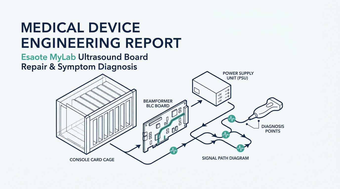
Esaote ultrasound systems—marketed under both the Esaote and Biosound Esaote brands across North America, Europe, Latin America, and Asia—utilize a modular card-cage architecture housed within the console chassis. Unlike monolithic laptop-style ultrasound devices where computing and acoustic processing are integrated onto a single multi-layer board, cart-based platforms such as the MyLab 60, MyLab 70, MyLab 70 XVision (Model 6150), MyLab 90 (Model 6100), MyLab Class C, MyLab Twice (Model 6200), and MyLab TwiceSix distribute acoustic transmit, receive beamforming, power transformation, digital signal reconstruction, and host PC processing across dedicated printed circuit board assemblies (PCBAs) 5 6.
When an electronic fault occurs in a clinical environment, replacing assemblies at random leads to unnecessary downtime, inflated parts costs, and risk of secondary damage to healthy boards. A successful diagnostic workflow requires mapping observable symptoms—such as system-wide boot failure, channel-specific dropouts, mode-specific artifacts, or unresponsive control surfaces—to the specific board sub-system responsible. For engineering teams evaluating broader multi-vendor fleets, this methodology mirrors our diagnostic frameworks for GE ultrasound board symptoms, Philips board symptoms, Siemens Acuson board symptoms, and Samsung Medison board symptoms, while addressing Esaote's unique proprietary board nomenclature.
| Sub-System Board Family | Proprietary Name / Abbreviation | Representative Part Numbers (9501xxx / P/N) | Primary Electronic & Acoustic Function | Dominant Failure Symptoms & Manifestations |
|---|---|---|---|---|
| Beamformer Line Channel Board | BLC Board / Channel Assembly | 9501099 (MyLab 70/ClassC/90), 9501076 (MyLab 15), 312445 | Contains multi-channel high-voltage transmit pulsers, low-noise preamplifiers (LNA), Time Gain Compensation (TGC) analog amplifiers, and analog-to-digital converters (ADCs) for acoustic line reception. | Vertical dark bands or dropout lines across the 2D ultrasound sector; localized loss of acoustic sensitivity; image granularity loss; channel noise artifacts across all probe ports. |
| Beamformer Sub-Controller Board | BSC Board / Beamformer Controller | 9501097 (MyLab Class C/60/70/90) | Executes real-time FPGA-based digital delay calculations, channel summation, dynamic receive focusing, and digital filtering for acoustic line reconstruction. | Complete loss of 2D acoustic image with active user interface; severe geometric distortion; acoustic beam defocusing; system freeze upon switching acoustic presets. |
| Beamformer Interface / Processing | BIP Board / Front-End Interface | 9501093 (MyLab 70), 9501212000 (TRX Board MyLab 50) | Routes digitized acoustic data between the front-end card cage and back-end processing; manages probe connector multiplexing and front-end synchronization clocks. | Intermittent communication loss between probe connector and beamformer; probe recognition failure across all ports; front-end synchronization errors during system boot. |
| Embedded PC Core / Mainboard | PC Module / CPU Motherboard | 330000055-00363 (Class C), 222022900 (TwiceSix), 9501361 (ML40), 9501361000 (ML15/25/30) | Runs embedded host operating system (Windows Embedded / proprietary BIOS), system management software, user database, network DICOM connectivity, and peripheral bus management. | System fails to initiate BIOS POST; continuous reboot loop; Windows blue screen / OS crash; freezing on initial splash screen; loss of Ethernet DICOM communication; corrupted user presets. |
| AC/DC Power Supply Assembly | PSU / Power Module | 9103472000 (Class C), 9707350000 (MyLab 50), 9501083010 (MyLab 25), 9501083 (MyLab 30) | Converts mains AC input (100–240V) to regulated DC power rails (+3.3V, +5V, +12V, -12V, +24V) for digital computing and regulated high-voltage (HV) rails (+/- 100V) for acoustic transmit pulsers. | Total no-power condition (no standby LEDs); cooling fans spin briefly and stop; intermittent random shutdowns under high acoustic power load (Color Doppler); high-voltage rail collapse causing black image. |
| Image & Transducer Routing | ITR Board / Transducer Routing Assembly | 9501089 (MyLab Twice90) | High-voltage relay and solid-state multiplexing matrix connecting multiple electronic probe sockets (cart ports) to the internal beamformer bus. | Failure of specific probe port while other ports operate normally; probe pin connector signal cross-talk; erratic acoustic switching when toggling between connected transducers. |
| Video & Back-End Processing | Video Board / Graphic Processor | 9501081 (MyLab 40), 9501079 (Doppler Board MyLab 25) | Performs digital scan conversion, color Doppler FFT flow processing, cine loop memory storage, and analog/digital video signal output (DVI, VGA, composite) to the primary display. | Loss of primary display video while console backlights operate; loss of PW Doppler or Color velocity map while 2D structure is normal; corrupted video overlay / graphics tearing. |
| Operator Control Panel Assembly | Control Panel / User Interface Sub-System | 9103491000 (MyLab Class C) | Integrates alphanumeric keyboard, Time Gain Compensation (TGC) slide potentiometers, rotary encoders, optical trackball, and secondary touchscreen controller. | TGC slide controls unresponsive; trackball cursor drifting or unresponsive; intermittent keyboard key lockup; touchscreen freeze; startup failure accompanied by blinking keyboard LEDs. |
Source: Esaote 61XX Service Manual Rev C and MyLab 70 Service Manual cross-referenced with Rongtao Medical verified catalog and inventory data
Understanding the distinction between these sub-systems prevents common misdiagnoses. For instance, a total loss of ultrasound image on a MyLab 70 can originate from a collapsed high-voltage DC supply rail from the Power Supply (9103472000), a timing failure on the BSC Board (9501097), or a digital scan-conversion fault on the back-end video processing chain. Biomedical engineers should cross-reference observed symptoms with established ultrasound board failure patterns to structure their fault-isolation workflow.
No power, no boot or random shutdown: PSU, PC/mainboard or a peripheral?
Power and boot anomalies represent the largest category of service calls on aging Esaote MyLab consoles. When a technician presses the power button and the system fails to enter clinical scanning mode, the fault generally isolates to one of three hardware domains: primary AC/DC power transformation, embedded PC motherboard startup, or peripheral communication lockups 5 10.
| Observed Failure Manifestation | Initial LED / Fan State | Primary Hardware Suspect | Engineering Verification & Safe Test Protocol | Recommended Corrective Action |
|---|---|---|---|---|
| Total System Inaction | No power indicator LEDs; cooling fans completely inactive; no relay click. | Mains Input Filter / Primary AC/DC Power Supply Unit (e.g. 9103472000 / 9707350000) | Verify external mains cord and circuit breaker; check console AC inlet fuse with DMM (continuity); measure standby DC output voltage (+5VSB) on power distribution harness with system disconnected from load. | Replace blown primary input fuses; if standby rails have collapsed or show thermal discoloration, replace or rebuild AC/DC PSU assembly. |
| Power-Up Pulse with Immediate Shutdown (0.5–2 sec) | Fans pulse momentarily; front standby LED flashes once and shuts down. | Secondary DC Rail Short / High-Voltage Rail Overcurrent in Card Cage | Disconnect all ultrasound probes; remove front-end BLC/BSC boards one by one from card cage; re-power system after each removal to detect overcurrent clamping. | Isolate shorted board pulling down DC rails (typically failed decoupling capacitor or shorted pulser IC on BLC 9501099); repair board at component level. |
| Continuous Boot-Loop / Splash Screen Freeze | Power LEDs solid; cooling fans run continuously; monitor freezes at Esaote logo or BIOS prompt. | Embedded PC Motherboard (e.g. 330000055-00363 / 9501361) / Corrupted Storage / CMOS Battery | Measure CMOS backup battery voltage (CR2032 < 2.8V indicates dead battery); reseat DDR RAM modules; connect external VGA monitor to PC core; inspect storage media (HDD/SSD) for bad sectors. | Replace CMOS coin cell and reset BIOS configuration; replace defective RAM module; re-image system software from official recovery archive onto validated medical-grade storage. |
| Startup Hang with Blinking Keyboard Backlights | Fans running; monitor remains dark or displays no sync; keyboard LEDs flash intermittently. | Incomplete PC POST / Front-Panel USB/Serial Communication Bus Contention | Disconnect internal USB/serial ribbon cable connecting Control Panel (9103491000) to PC core; attempt boot with standard external USB keyboard. | Reseat internal control panel interface harness; clean gold card-edge connectors; if blinking persists, service control panel interface board 10. |
| Random Thermal Shutdown During High-Output Scanning | System boots and operates in 2D mode, but suddenly powers off during continuous Color Doppler / elastography. | PSU High-Voltage Thermal Protection / Degraded Card Cage Cooling Fans | Inspect chassis air intake filters for lint accumulation; verify all internal axial fans spin at rated RPM; inspect PSU electrolytic capacitors for bulging or electrolyte leakage. | Clean air filters; replace failing chassis cooling fans; rebuild PSU DC filtering stages to eliminate voltage sag under peak acoustic power loads. |
Source: Compiled from Esaote 61XX technical service manuals, MedWrench community engineering cases, and Rongtao Medical hardware diagnostic logs
A critical distinction in power diagnosis involves differentiating primary power supply failure from embedded PC architecture problems. In legacy models like the MyLab 50 XVision, service engineers frequently encounter BIOS configuration loss caused by a depleted lithium coin-cell battery on the PC motherboard (P/N 9501361000). When the battery discharges below 2.8V, the motherboard loses its CMOS parameters, resulting in an unconfigured boot sequence where the system halts before loading the ultrasound application 8. Technicians should replace the battery and restore factory BIOS defaults before assuming the PC mainboard has failed.
For biomedical engineering teams managing power supply failures, refer to our detailed technical analysis on ultrasound power supply failure, no-power, and boot-loop isolation. When isolating multi-brand fleet issues, compare Esaote's power behavior against GE ultrasound board symptoms and Philips ultrasound board symptoms.
Dead channels or dropout: is it the probe, the front-end or the BSC/BLC beamformer-channel boards?
Acoustic dropouts—visible as vertical black or dark shadows extending from the near field to the far field of the ultrasound image—are among the most common clinical complaints reported by sonographers. Because both a damaged transducer (cracked piezoceramic crystals, broken micro-coaxial cable wires, or damaged acoustic lens) and a defective beamformer line channel board (BLC) produce identical dark lines in the ultrasound sector, rigorous localization is essential 5 6.
To determine whether the fault resides within the transducer or inside the Esaote card cage, clinical engineering teams must execute a two-stage localization protocol before dismantling the console:
- The Cross-Port Swap Test: Move the suspect probe (e.g. CA541 convex or LA523 linear) from Port 1 to Port 2 and Port 3 on the console connector manifold. If the vertical shadow moves with the probe to every port, the fault is isolated to the transducer assembly (cable harness, connector pin, or crystal array). If the shadow remains present on only one specific socket across multiple known-good probes, the fault resides in the Image & Transducer Routing (ITR) board or socket relay.
- The Known-Good Probe Cross-Check: Connect a known-good probe of the same model family to the system. If the vertical shadow appears at the exact same geometric azimuth angle across multiple different probes and across all active ports, the fault is definitively inside the beamformer card cage (BLC Board 9501099 or BSC Board 9501097).
- In-Air Acoustic Reverberation Assessment: Hold the probe face in air with acoustic gain elevated. An intact transducer and beamformer array will display a uniform, horizontal reverberation ring-down pattern across the near field. A missing vertical segment in the reverberation band confirms channel dropouts in the corresponding crystal/channel group.
| Acoustic Artifact Pattern | Probe Swap Behavior | Isolated Fault Domain | Root Cause Electronic Mechanism | Corrective Service Action |
|---|---|---|---|---|
| Single Narrow Vertical Dark Line (< 2–4 crystal width) | Follows probe when moved across different ports; absent with secondary probe. | Transducer Assembly (Acoustic Array / Cable) | Broken micro-coaxial conductor wire inside probe strain relief or fractured acoustic crystal element. | Route transducer to qualified ultrasound probe repair for cable re-termination or crystal array replacement. |
| Wide Vertical Shadow / Multi-Channel Block Dropout (8, 16, or 32 channels) | Persists at exact same screen location across all connected probes and all ports. | Beamformer Line Channel Board (BLC 9501099 / 9501076) | Failed multi-channel pulser IC, open transmit high-voltage protection diode, or defective Low-Noise Amplifier (LNA) channel group on BLC PCBA. | Extract BLC board; clean card-edge connectors with isopropyl alcohol; replace board with tested spare or submit for component-level repair. |
| Uniform Haze / High-Gain Acoustic Snow across Entire Sector | Present on all probes; increases when Doppler or Color flow modes are activated. | Analog Control / High-Voltage Power Supply Rail Ripple | Excessive AC ripple voltage on +/- 100V high-voltage DC pulser rails due to drying electrolytic filter capacitors in PSU (9103472000). | Scope high-voltage rails under active acoustic load; rebuild or replace primary AC/DC power supply assembly. |
| Complete Loss of Color & PW Doppler with Normal 2D B-Mode | Occurs across all Doppler-capable probes; 2D structural anatomy renders with normal resolution. | Dedicated Doppler Processing / Back-End FFT Board (e.g. 9501079) | Failure of dedicated digital signal processor (DSP), corrupted Doppler filter coefficients, or high-speed demodulation memory fault. | Inspect back-end DSP boards; re-seat mezzanine processor cards; replace Doppler processing PCBA. |
| Geometric Image Shear / Lateral Distortion | Image appears distorted horizontally; sector angle narrows or displays banding. | Beamformer Sub-Controller (BSC 9501097) | Timing jitter or clock distribution failure across beamformer FPGA delay calculation pipeline. | Replace BSC controller board with matching firmware revision; verify clock synchronization signals. |
Source: Esaote service manual diagnostic trees cross-referenced with multi-brand acoustic bench test protocols
For a comprehensive engineering review of acoustic localization methodologies, refer to our clinical engineering guides on ultrasound beamformer front-end board failure and image artifacts: probe vs scanner diagnosis.
How do I verify a 9501xxx board part number and revision before ordering?
Esaote and Biosound Esaote utilize a proprietary part-numbering taxonomy that service managers and biomedical engineers must interpret correctly before purchasing replacement boards or requesting repair quotes. The majority of internal printed circuit board assemblies are identified by a 9501xxx series number, which appears either as a 7-digit integer (e.g. 9501099, 9501097, 9501089) or as an expanded 10-digit format with trailing revision zeros (e.g. 9501212000, 9501361000, 9501222000) 9.
In addition to the 9501xxx series, certain major modular sub-assemblies—such as power supplies, control panels, and computing modules—utilize secondary numbering schemes (e.g. 9103472000 for Class C AC power supplies, 9103491000 for Class C control panels, 222022900 for TwiceSix PC modules, and 330000055-00363 for Class C PC assemblies).
| Console Platform Compatibility | Assembly Name | Exact Part Number (P/N) | Format & Catalog Reference | Engineering Notes & Revision Considerations |
|---|---|---|---|---|
| MyLab 70 / Class C / MyLab 90 | Beamformer Line Channel Board (BLC) | 9501099 | 7-digit — verified catalog listing | Multi-channel transmit/receive board. Must verify board revision code on barcode sticker; matched pairs recommended across card cage slots. |
| MyLab Class C / 60 / 70 / 90 | Beamformer Sub-Controller (BSC) | 9501097 | 7-digit — verified catalog listing | Central beamformer control board. Firmware EEPROM must align with console system software version to avoid boot communication mismatch. |
| MyLab Class C | Embedded PC Module Assembly | 330000055-00363 | Alphanumeric — verified catalog listing | Host computing engine. Includes processor, RAM, and embedded display controller. Requires proper BIOS configuration for video output. |
| MyLab Twice90 | Image & Transducer Routing Board (ITR) | 9501089 | 7-digit — verified catalog listing | Transducer routing interface. Connects high-density probe connectors to internal acoustic signal buses. |
| MyLab TwiceSix | Host PC Motherboard Assembly | 222022900 | 9-digit — verified catalog listing | Specialized computing module for TwiceSix dual-screen architecture. Requires compatible system software build. |
| MyLab Class C | Operator Control Panel Assembly | 9103491000 | 10-digit — verified catalog listing | Complete user interface module. Integrates TGC potentiometers, keyboard PCB, and trackball assembly. |
| MyLab Class C | AC Power Supply Unit (PSU) | 9103472000 | 10-digit (verified inventory listing, 90-day warranty) | Full chassis AC/DC power supply providing system logic rails and acoustic transmit voltages. |
| MyLab 50 | Front-End Transceiver Board (TRX) | 9501212000 | 10-digit (documented legacy repair coverage) | Transmit/receive analog interface for MyLab 50 portable cart console. |
| MyLab 70 | Beamformer Interface Board (BIP) | 9501093 | 7-digit (documented legacy repair coverage) | Card-cage synchronization and probe interface routing for MyLab 70 platform. |
Source: Rongtao Medical verified multi-brand parts catalog and inventory repository records
To ensure zero-error parts procurement, clinical engineering teams must follow a strict 5-point verification checklist before placing orders:
- Inspect Physical Barcode Stickers: Locate the white adhesive label on the component side of the PCBA. Record both the printed part number (e.g.
9501099) and the secondary serial/lot number. - Verify Board Revision Letters/Numbers: Check the etched copper markings (e.g.
REV C,REV 02) and stamped revision boxes on the PCB silkscreen. Certain board families require matched revisions when populated in pairs. - Check Firmware & Software Compatibility: Confirm the host console software release. Certain digital boards (BSC, PC modules) require matching firmware configurations to prevent bus communication lockup.
- Photograph Both Sides of the Board: Capture clear, high-resolution photographs showing overall component layout, connector pin integrity, and close-ups of all identifying labels.
- Cross-Link Incoming Acceptance Testing: Follow standardized receiving protocols as outlined in our comprehensive guide on how to verify an ultrasound board part number and manage acceptance testing.
What does the FDA record show for the MyLab family — clearances, recalls and known issues?
A comprehensive engineering evaluation of any diagnostic imaging platform requires analyzing its public regulatory history. In the United States, medical device clearances, enforcement reports, and establishment registrations maintained by the Food and Drug Administration (FDA) provide an objective record of platform architecture, model evolution, and field safety actions 1 2 3.
Analysis of FDA 510(k) Premarket Notification data shows 140 clearances granted to Biosound and Esaote between April 4, 1983 (K837063, Biosound Surgiscan) and April 6, 2026 (K253288, MyLabE80/E85). This regulatory timeline documents the architectural progression across four decades of ultrasound engineering:
| FDA 510(k) Number | Clearance Date | Official Cleared Device Name | OEM Model Number Mapping | Architectural Significance & Technological Milestone |
|---|---|---|---|---|
| K837063 | 1983-04-04 | Biosound Surgiscan | Legacy Analog Platform | Foundational premarket clearance establishing Biosound surgical and vascular ultrasound systems in the US market. |
| K051308 | 2005-06-01 | MyLab 70 Ultrasound Imaging System | Model 6150 Platform | High-end digital platform introducing modular BLC/BSC beamformer architecture and high-density transducer interfaces 1. |
| K051837 | 2005-07-20 | MyLab 90 Diagnostic Ultrasound System | Model 6100 Platform | Premium cardiovascular and general imaging cart system expanding card-cage processing power and high-voltage pulser channels. |
| K052805 | 2005-10-17 | MyLab 30, MyLab 50, MyLab 70 | Models 7300, 7350, 6150 | Multi-platform unified architecture introducing shared embedded software, modular power supplies, and common probe interfaces. |
| K060827 | 2006-05-19 | MyLab 30 / 50 / 70 / 90 3D/4D Additions | Models 7300 / 7350 / 6150 / 6100 | Integration of motorized 3D/4D volume transducer controllers and high-speed back-end reconstruction engines. |
| K081386 | 2008-09-25 | MyLab 70 / MyLab 90 Updates | Model 6150 (MyLab 70), Model 6100 (MyLab 90) | Formal regulatory confirmation of OEM model numbering; enhanced elastography and advanced Doppler calculation algorithms. |
| K100931 | 2010-06-25 | MyLabTwice Ultrasound System | Model 6200 Platform | Dual-modality platform combining high-end cart console architecture with integrated portable MyLabSat satellite scanning unit. |
| K230179 | 2023-11-29 | MyLabX90 Diagnostic Ultrasound System | Model 6440 | Modern architecture featuring augmented computing architecture and single-crystal matrix transducer support 4. |
| K241671 / K253288 | 2025-05-16 / 2026-04-06 | MyLabE80 / MyLabE85 Ultrasound Systems | Model 6450 Platform | Current-generation shared-service cart systems with updated digital beamforming electronics. |
| K243253 / K253310 | 2025-06-18 / 2025-11-25 | MyLabA50 / A70 & MyLabC25 / C30 | Current Mid-Range & Compact Lines (Models 6600 / 7600) | Latest generation compact and point-of-care ultrasound platforms. |
Source: U.S. FDA 510(k) Premarket Notification Database records
Beyond clearances, FDA enforcement and recall databases provide valuable operational intelligence for maintenance teams. Between 2014 and 2025, the FDA recorded 10 Class II enforcement actions concerning Esaote and Biosound devices (all 10 classified as Class II, with 9 directly involving ultrasound systems, transducers, or power supplies) 2:
- 2018 Thermal Management & Probe Temperature Actions (Models 6100, 6150, 6200, 6250): In January 2018, FDA recorded Class II recall enforcement reports for MyLab consoles (covering MyLab 90 Model 6100, MyLab 70 Model 6150, MyLabTwice Model 6200, and Model 6250). The action addressed potential transducer surface overheating when operating specific probes (BL433, C18, CA541, EC1123, and PA023E) in user-defined operating presets, resolved through system software temperature-limiting updates 2.
- 2018 Probe Power Monitoring Software Settings (Seven, Gamma, Alpha): In June 2018, Class II actions addressed probe power monitoring software parameters across portable and cart models (Model 6400 MyLab Seven, Model 7410 MyLab Gamma, Model 7400 MyLab Alpha).
- 2020 AC/DC Power Supply Adapter Recall (Model 7400): In September 2020, FDA recorded a Class II recall for external AC/DC power supply adapters (XP Power AHM180PS19, Part Numbers 151004300 and 151004301) used with portable MyLab Alpha systems, after reports that adapter connectors could heat up, generate smoke and melt 2.
- 2025 Endocavity Probe Corrective Action: In March 2025, a Class II recall was initiated for Model E 3-12 endocavity probes after a potential weakness was identified in the probe body that could allow liquid to leak from the casing near the cable in a specific production batch.
Strict Regulatory Context & Guardrails: Healthcare technology managers must interpret recall and enforcement reports within their proper regulatory context. Recall counts reflect proactive manufacturer reporting, field safety corrective actions, and software patch distributions; they do not measure product failure rates, clinical incidence, or comparative reliability between OEM brands. Furthermore, FDA Manufacturer and User Facility Device Experience (MAUDE) passive surveillance data contains essentially zero adverse-event reports for Esaote consoles across historical sampling years (e.g. 0 rows in 2018, 2024, and 2026; 4 rows in 2020). As with all passive surveillance data, absence of reports reflects reporting patterns rather than absolute clinical safety. For broader regulatory frameworks, review our analyses of FDA ultrasound recall failure modes and MAUDE malfunction report trends.
Repair, tested replacement or donor system: how to decide for a legacy MyLab fleet?
When an electronic board fails on an installed MyLab console, service managers face three primary remediation options: submitting the defective board for component-level repair, purchasing a tested replacement board from verified inventory, or harvesting parts from a retired donor console 9. Selecting the optimal route requires balancing downtime urgency, parts availability, cost, and risk.
| Decision Parameter | Component-Level Board Repair | Tested Replacement PCBA | Donor System Harvesting |
|---|---|---|---|
| Typical Turnaround Time | 5 to 8 business days (standard repair cycle) plus shipping transit. | Fastest when an exact-match tested unit is in stock; current availability and dispatch timing are confirmed through the live catalog and quote. | Immediate (if donor system is physically on-site). |
| Economic Impact | Typically the lowest total-cost route: the hospital's original board is restored rather than replaced. | Moderate: below sourcing a comparable OEM module, while preserving capital budget. | Zero direct purchase cost, but carries high hidden labor and inventory holding expenses. |
| Part Number & Revision Certainty | 100% exact match (the hospital's original board is repaired and returned). | High; requires strict pre-shipment barcode and revision verification. | Variable; donor systems often carry different hardware revisions or incompatible firmware. |
| Quality & Testing Assurance | High; repaired boards undergo ultrasonic cleaning, component replacement, and 48-hour real-machine testing in an actual ultrasound system. | High; inventory units validated under 48-hour continuous real-machine load testing. | Lowest; donor parts carry unknown operating hours, thermal stress, and aging electrolytic capacitors. |
| Warranty Coverage | Typically 90-day comprehensive warranty on repaired circuit stages. | Typically 90-day replacement warranty on complete tested assemblies. | Zero warranty; failure risks recurring immediately upon clinical deployment. |
| Best Suited Clinical Scenario | Non-urgent clinical backup systems, rare board variants with zero market stock, or planned maintenance. | High-volume clinical departments where console downtime causes immediate patient backlog. | Emergency temporary stabilization while a certified replacement board is in transit. |
Source: Rongtao Medical clinical engineering service economics model
Regardless of whether a board is repaired or replaced, clinical engineering teams must demand rigorous quality evidence before installing hardware into active patient scanners. For complete economic frameworks, consult our comprehensive analyses on ultrasound board repair vs replacement and urgent ultrasound parts sourcing.
Real-Machine Testing Gate: Validating an ultrasound PCBA cannot be accomplished with basic handheld multimeters on an unpowered bench. Reliable verification requires a dedicated ultrasound console running continuous diagnostic passes for a minimum of 48 hours under full thermal and acoustic load. A complete test pack includes DC voltage rail stability logs under peak pulser draw, thermal imaging profiles to detect hot-spotting ICs, phantom acoustic resolution checks, and transducer recognition logs across all ports as detailed in our guide on ultrasound board real-machine test evidence packs.
Safe Servicing & Electrical Safety Boundaries: Servicing ultrasound electronics involves serious electrical hazards. Never attempt to service energized consoles or touch internal power supply stages without following lock-out/tag-out (LOTO) protocols and discharging high-voltage electrolytic capacitors. Never bypass chassis interlocks, defeat electrical ground paths, or use unauthorized component substitutions. Following any board replacement or power supply repair, the console must undergo comprehensive electrical safety testing—measuring protective earth resistance, chassis leakage current, and patient leakage current in accordance with IEC 62353 / IEC 60601-1 standards—followed by phantom image calibration before being released for clinical patient scanning.
Where Rongtao Medical fits — and where it does not
Understanding the precise commercial and technical scope of a service partner is vital for healthcare procurement officers and biomedical engineering directors. Rongtao Medical operates as an independent multi-brand ultrasound service provider and parts specialist 9:
- Where Rongtao Medical Fits: Rongtao provides advanced component-level electronic repair for Esaote MyLab PCBAs (including BLC channel boards, BSC controllers, PC modules, and power supplies), maintaining a standard 5–8 business-day turnaround and typically 90-day warranty. Rongtao maintains extensive inventory of tested replacement parts—such as BLC 9501099, BSC 9501097, PC 330000055-00363, Control Panel 9103491000, and AC PSU 9103472000—each backed by 48-hour real-machine testing and high-resolution pre-shipment photographs. Global express logistics (DHL, FedEx, UPS) support bonded-zone outbound dispatch to over 140 countries 9.
- Where Rongtao Medical Does Not Fit: Rongtao Medical is an independent third-party service organization and is not an authorized distributor, representative, or affiliate of Esaote S.p.A. OEM brand names and model numbers are cited exclusively for equipment compatibility and identification purposes. Rongtao does not sell proprietary OEM software licenses, and all repair services are performed in accordance with independent quality management standards.
To request an immediate, actionable quote for Esaote MyLab board repair or tested replacement parts, service engineers can utilize our standardized multi-brand ultrasound board repair RFQ template or contact our technical support desk directly via our Biosound Esaote board repair department. Please provide the following technical details with your inquiry:
- Exact ultrasound system model (e.g. MyLab 70 XVision Model 6150, MyLab Class C, MyLab Twice Model 6200).
- Exact board part number (7-digit or 10-digit 9501xxx series, or modular P/N) and hardware revision letter/number.
- Clear, high-resolution photographs of both sides of the board, focusing on barcode labels, soldered components, and connectors.
- Detailed symptom description, including boot behavior, on-screen error codes, artifact patterns, and probe swap test results.
- Required service type (component-level repair vs tested replacement unit), quantity, and destination country for bonded logistics calculation.
Frequently Asked Questions (FAQ)
Are Esaote MyLab 60/70/90, ClassC and Twice boards still repairable at component level?
Yes. Most electronic boards across these platforms—including BLC channel boards (9501099), BSC controllers (9501097), ITR routing boards (9501089), PC motherboards, and internal AC/DC power supplies (9103472000)—are fully repairable at the component level. Common repairs involve replacing shorted high-voltage transmit pulsers, failed low-noise preamplifiers, blown DC filtering capacitors, surface-mount diodes, and corrupted EEPROM firmware chips. Component-level repair restores original factory electrical specifications at a fraction of the cost of whole-system replacement.
Do service manuals and schematics exist for Esaote MyLab systems?
Yes. Technical documentation—such as the Esaote 61XX Service Manual (Rev C covering ML60 and ML70XV) and the MyLab 70 Service Manual—circulates through public technical archives and clinical engineering communities 5 6 7. These manuals provide card-cage block diagrams, board disassembly steps, power supply pinouts, and field test procedures. For complex component-level circuit trace analysis, specialized repair centers utilize proprietary test rigs and comparative circuit schematics.
What is the typical turnaround and warranty for MyLab board repair?
Standard component-level board repair turnaround is typically 5 to 8 business days upon arrival at our technical repair center; the final turnaround for a specific board is confirmed with the quote. Repaired boards carry a typical 90-day comprehensive warranty covering all replaced components and associated circuit stages. When an exact-match tested unit is in stock, replacement is typically the fastest route; current availability, dispatch timing and warranty terms are confirmed per item through the live catalog and quote 9.
Does Rongtao support MyLab 15/25/30/40/50 boards beyond the current catalog SKUs?
Yes. Rongtao's documented technical repair archive spans more than 80 legacy Biosound Esaote product notes—including MyLab 15 channel boards (9501076, 312445), MyLab 25 Doppler boards (9501079) and power supplies (9501083010), MyLab 30 power boards (9501083), MyLab 40 video boards (9501081), MyLab 50 TRX boards (9501212000), and mainboards (9501361, 9501361000) 9. Even when specific legacy boards are not listed in active online catalog inventory, component-level repair and custom parts sourcing remain fully supported upon technical request.
What should I include when requesting an Esaote MyLab board-repair quote?
To receive an immediate, fixed-price quote, provide the console model (e.g. MyLab Class C), the 9501xxx part number and revision from the white barcode sticker, clear photos of the front and back of the PCBA, a concise description of the observed fault symptom (such as no power, vertical channel dropout, or freezing), the required quantity, and your shipping destination city and postal code.