
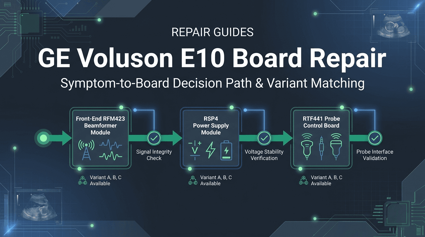
Which Voluson E10 board domain does my symptom point to?
When a flagship GE Voluson E10 premium women's health ultrasound system develops an electronic failure, clinical operations in high-throughput OB/GYN, maternal-fetal medicine (MFM), or reproductive endocrinology departments come to an immediate halt. Because the Voluson E10 represents GE's high-channel-count, matrix-array imaging platform—originally introduced to power advanced electronic 4D (e4D) matrix transducers alongside standard mechanical volume probes 6—its internal electronic layout is substantially more complex and densely integrated than standard general-imaging scanners.
Field service engineers, hospital biomedical equipment technicians (BMETs), and independent service organizations (ISOs) facing an inoperative E10 frequently make two costly errors: either prematurely declaring the entire console unserviceable and initiating an emergency capital replacement, or blindly ordering replacement boards based on general model names without verifying the underlying hardware variant and part numbers. A rigorous diagnostic approach begins by isolating the failure to one of four primary electronic functional domains based on objective system behavior.
| Clinical & Service Symptom | Probable Subsystem Domain | Primary Candidate Board Assembly | Key Verified Part Numbers / Labels | Mandatory Isolation & Verification Gate |
|---|---|---|---|---|
| Total loss of echo / black acoustic field across ALL connected probes; 2D B-mode shows only graphic overlays or faint noise. | Acoustic Front-End & Beamformer | RFM423 / RFM323 Front-End Mainboard | KTZ304074 (RFM423 EC320), KTZ304142 (RFM423-2), KTZ304074-R / 5729200-8 (RFM423F), KTZ304141 / 5809347-5 (RFM323H) | Confirm fault persists across at least two distinct probe types (e.g. convex C1-5-D and linear 11L-D) on different probe ports. Verify front-end DC supply rails (+/-HV, +5V, +12V) before removing module. |
| System begins boot sequence; power collapses, fans spin down, or unit resets 3 to 10 seconds into boot before loading Windows / application. | Power Conversion & Distribution | RSP4 Power Supply Module / Main Power Supply (PSU) | KTZ304148 (RSP4 Module) | Disconnect all peripheral USB/video cables and card cage board loads sequentially. Measure DC stand-by rails (+3.3VSB, +5VSB) and verify Power-Good logic transition. |
| 2D imaging operates normally on standard probes, but electronic 4D (eM6C) or mechanical volume probes drop out, fail initialization, or produce severe slicing artifacts. | Matrix Probe Control & Volume Processing | RTF441-EC320 Probe Control Board / RTF TI Board | KTZ304082 (RTF441-EC320 256ch e4D), KTZ303955 (RTF TI Board) | Inspect probe connector pins for bent contacts. Test with a known-good standard 2D probe and secondary volume probe to separate transducer motor/matrix failure from internal RTF control logic. |
| Console boots normally; main display shows ultrasound application; operator touch screen, rotary encoders, TGC sliders, or trackball are dark or unresponsive. | User Interface & Control Surface | Control Panel Assembly / RTV30A Board | KTI303820-9 (Control Panel PCB), KTI301890 (Panel Assy), KTI303517-5 (RTV30A.P2), KTZ304229 / 5729168-14 (White Panel) | Check secondary DC power delivery to the control panel pedestal. Inspect internal USB communication ribbon cables and reseat the RTV30A interface PCBA. |
| Boot freezes at BIOS POST screen, Windows blue-screen error occurs during boot, or system locks up intermittently during Cine loop playback. | Host Computing & Back-End Processing | Back-End Processor (BEP) / Host Motherboard / System Storage | 5747700-6 (GEB3110 board, cataloged E10 assembly), System SSD / RAM modules | Export diagnostic error logs if accessible; inspect motherboard CPU/chipset cooling fans for dust clogging; execute memory diagnostics and verify DC voltage stability to the BEP cage. |
| Severe image artifacts, missing scan lines, acoustic shadow banding, or temperature warning confined to a SINGLE connected probe. | Transducer & Probe Interface | Ultrasound Probe Assembly / Probe Port Receptacle | Transducer Model (e.g., IC9-RS J48691PJ, RAB6-D, C1-5-D, 11L-D) | Swap probe to an adjacent console port; cross-test probe on a sibling Voluson system. Verify transducer against active FDA recall notices (specifically Open Recall Z-0865-2024 on IC9-RS). |
Understanding this high-level architecture prevents misdiagnosing a simple power supply failure as a catastrophic front-end breakdown, or condemning a healthy console when an actively recalled probe assembly is the true root cause. In the following sections, each electronic subsystem domain is evaluated with exact part-number mappings, component failure mechanisms, and verified bench repair paths.
No echo on all probes or a boot-time front-end error: the RFM423 front-end family — and which variant fits my system?
Among all failure modes encountered on the GE Voluson E10, the most clinically disruptive is the sudden loss of ultrasound echo across all connected transducers 9 13. In this failure state, the console completes its operating system boot sequence and launches the Voluson imaging software without crashing; however, when the sonographer activates any probe port (whether a linear, convex, phased array, or volume transducer), the 2D B-mode display presents a completely black acoustic image area. Depth markers, patient demographics, and menu graphics remain crisply rendered, but acoustic reflections are entirely absent or reduced to faint baseline noise or uniform whitish/foggy display washouts documented in field service reports — a symptom our own legacy field note on the Voluson E10 whitish-image fault also records 14.
Alternatively, the system may halt during hardware initialization with a diagnostic dialog indicating a front-end communication failure or beamformer timeout, preventing the software from entering active scanning mode 9. Both symptoms point directly to the system's radio-frequency module (RFM) front-end card cage, dominated by the RFM423 / RFM323 beamformer family, as frequently discussed across clinical engineering forums and service teardowns 11 12.
The RFM423 is a sophisticated multi-layer printed circuit assembly that executes 256-channel digital transmit pulse generation, programmable high-voltage transmit steering, and ultra-low-noise pre-amplification and analog-to-digital conversion of incoming acoustic echo signals 5 8. Within the Voluson E10 lifecycle, several major variants of this front-end module were manufactured to accommodate evolving continuous-wave (CW) Doppler sub-boards, matrix array channel multiplexing, and backplane bus revisions.
| Module Designation | Verified OEM Part Numbers | Hardware Architecture & Features | Observed System Era / Revisions | Interchangeability & Replacement Rules |
|---|---|---|---|---|
| RFM423 EC320 | KTZ304074 / 5729200 | 256-channel front-end mainboard; EC320-generation label carried in Rongtao repair records covering Voluson E6/E8/E10. | Recorded with a BT17 label in Rongtao's E10 part archive. | Direct replacement for matching KTZ304074 units; repair includes channel calibration on a live E10 chassis. GE's parts store groups the RFM423 family across Voluson E6/E8/E10 — exact fit still depends on matching the variant and revision printed on the board label. |
| RFM423-2 FE-Mainboard | KTZ304142 | 256-channel FE-Mainboard without MUX; listed by GE as the SCW (steerable continuous-wave) configuration of the RFM423 family. | Mid to late Voluson E10 platforms (BT15-BT20 labels in Rongtao records); listed in the official GE HealthCare Service Shop catalog 5. | Match the SCW configuration to the system's original build: on some platforms the SCW function is delivered through the separate RSX20 extension-board family rather than the mainboard, so confirm which configuration the chassis uses before ordering. |
| RFM423F | KTZ304074-R / 5729200-8 | Revision of the RFM423 family carried in Rongtao's verified stock records under the full -R part-number string. | Mature Voluson E10 production units; live stock row in Rongtao inventory (verify current availability through the catalog) 8. | Match the full KTZ304074-R/5729200-8 label string like-for-like; treat it as part-number-locked rather than assuming interchangeability with other KTZ304074 revisions. Installation requires element-by-element channel calibration. |
| RFM323H.P20 | KTZ304141 / 5809347-5 | RFM323-family front-end module carried in Rongtao's verified E10 stock records. | Voluson E10 configurations specifying this assembly (live stock rows in Rongtao inventory) 8. | Strict part-number lock: only install where KTZ304141 or 5809347-5 is physically specified on the defective assembly. |
When an RFM423 module fails, component-level diagnostic triage at a qualified repair facility isolates the breakdown to specific electronic failure mechanisms: (1) breakdown of high-voltage multiplexer ICs or transmit pulser FET arrays damaged by acoustic energy transients; (2) localized failure of low-noise preamplifier (LNA) chips across specific channel groups, causing vertical banding or total signal drop; (3) DC power rail filter capacitor degradation causing excessive ripple on analog lines; or (4) FPGA communication controller lockup preventing probe enumeration.
In Rongtao Medical's documented case archive, three Voluson E10 consoles trace this exact path: a B-mode image anomaly across all probes resolved by replacing the RFM module (case 001, public case page with bench photos); a boot-time RFM error that blocked scan mode, confirmed through diagnostic logs and resolved by a module rebuild (case 009); and an all-probes no-echo fault isolated to the RFM423 and resolved through channel rework with element-by-element calibration (case 010). Each returned to service within the typical 5-8 business-day turnaround, and under Rongtao's QA process every repaired board is released only after 48-hour real-machine testing 9. For broader context on beamformer circuitry across ultrasound brands, consult our technical analysis on ultrasound beamformer front-end board failures.
Power drop on boot or will not power on: RSP4 power module, PSU or motherboard?
Power delivery on the GE Voluson E10 is managed by a multi-stage power distribution architecture engineered to supply hundreds of watts of tightly regulated DC power across diverse voltage domains—ranging from low-voltage digital rails for high-speed processors and FPGAs to isolated high-voltage rails required for acoustic transducer pulsing 8 10.
A primary failure pattern encountered in clinical service is the sudden power collapse on boot. The operator presses the console standby power switch; cooling fans spin up; power indicator LEDs illuminate on the control panel; but within 3 to 10 seconds—well before the BIOS post screen completes or the Windows operating system begins loading—the entire console abruptly shuts down, often accompanied by an audible relay click. In some cases, the system enters an endless auto-restart loop.
Isolating this failure requires distinguishing between the interconnected power assemblies:
- RSP4 Power Supply Module (KTZ304148): The primary switched-mode AC/DC power supply assembly located in the lower chassis. It rectifies mains AC into primary high-current DC rails. Over 5 to 8 years of clinical operation, bulk electrolytic filter capacitors suffer electrolyte desiccation due to thermal stress, leading to high equivalent series resistance (ESR) and voltage sag under inrush load. When the front-end card cage attempts to initialize, the voltage drop triggers internal under-voltage lockout (UVLO) or over-current protection (OCP), causing an immediate shutdown 9 10.
- Back-End / Host Board Power Faults (e.g., the cataloged GEB3110 board, 5747700-6): Shorted point-of-load (POL) regulator FETs or tantalum bypass capacitors on host-computer boards can present a direct short-circuit to ground on a main DC rail, immediately tripping the power supply upon power button actuation 8.
In Rongtao's documented case 011 (Voluson E10 Main Power Supply), an E10 suffering power drop on boot was traced to the main power supply and resolved with a rail rebuild and capacitor refresh; a 48-hour live-system burn-in confirmed stable startup, restoring the console at a fraction of the cost of sourcing a complete new OEM power cage 9. For a detailed breakdown of power supply failure modes, review our guide on ultrasound power supply failure, no-power, and boot loops.
4D/volume-probe dropout with healthy 2D: the probe, the RTF441/EC320 probe-control path, or the front end?
The defining clinical capability of the GE Voluson E10 is its advanced volume imaging suite—specifically its support for electronic 4D (e4D) matrix array transducers (such as the GE eM6C curved electronic matrix probe) alongside conventional mechanical volume transducers (such as the RAB6-D and RIC5-9-D) 6. Unlike mechanical volume probes that utilize internal stepper motors and drive cables to physically oscillate an acoustic crystal array, electronic 4D matrix probes contain thousands of micro-machined 2D matrix transducer elements capable of steering acoustic beams electronically in both azimuth and elevation planes simultaneously.
A complex clinical scenario arises when standard 2D imaging functions perfectly across all transducers, but activating 4D/volume mode triggers an immediate failure: the volume acquisition freezes, the software displays a 'Volume probe initialization error' or 'Motor drive failure', or the rendered 3D volume shows severe geometric distortion and missing slice planes.
Isolating this failure requires walking through a three-stage diagnostic path:
- Stage 1 — Transducer Type & Motor Isolation: If the failure occurs on a mechanical volume probe (RAB6-D or RIC5-9-D), the issue is frequently mechanical: a broken internal drive wire, motor potentiometer wear, or bubble formation in the acoustic oil dome. Test a second mechanical volume probe. If a second mechanical probe functions properly, the console electronics are healthy and the defective probe should be routed to a specialized ultrasound probe repair facility.
- Stage 2 — RTF441-EC320 e4D Matrix Control Board (KTZ304082): If the failure occurs specifically with electronic matrix transducers (eM6C) or spans both mechanical and matrix volume modes across all ports, the root cause isolates to the RTF441-EC320 Probe Control Board (Part Number KTZ304082) or the associated RTF TI Board (KTZ303955) 8 10. The RTF441 manages the high-speed serial control lines, matrix micro-beamformer synchronization clocks, and high-current motor drive sequencing from the chassis to the probe receptacle.
- Stage 3 — Probe Port Interface & Connector Pins: Inspect the gold-plated pins within the console's probe connector ports. Bent, retracted, or contaminated connector pins on the high-density e4D matrix interface channels will interrupt the high-speed LVDS communication bus between the RTF441 and the transducer's internal micro-beamformer ASICs.
Catalog records confirm verified availability for both the RTF TI Board KTZ303955 and legacy part notes for the RTF441-EC320 Probe Control Board KTZ304082 8 10, providing verified board replacement and component-level repair options for specialized 4D subsystem faults.
Frozen, dark or unresponsive control panel: panel assembly, RTV30A board or motherboard?
The operator user interface of the GE Voluson E10 consists of an articulated console surface featuring an integrated capacitive touch screen, backlit push-buttons, time-gain compensation (TGC) slide controls, rotary optical encoders, an optical trackball, and an alphanumeric keyboard 8. When the control surface malfunctions, clinical scanning is paralyzed even if the acoustic front-end and back-end computing engines are fully functional.
Common control panel failure modes include: (1) touch screen display remains dark while backlit buttons illuminate; (2) touch screen registers phantom touches or fails touch calibration; (3) rotary encoders skip values or fail to adjust gain/depth; (4) TGC sliders fail to respond or chatter continuously; or (5) complete unresponsiveness across the entire physical operator surface.
Triage isolates the fault to three specific hardware assemblies:
- RTV30A User Interface Control Board (KTI303517-5 / KTI303517): The interface board family Rongtao's records group with the E10 control-panel path; when its firmware or local power regulation fails, the entire operator surface can appear dead while the rest of the console keeps running 8 10. Verified in the catalog as RTV30A.P2 KTI303517-5 and documented in legacy part notes 10.
- Control Panel Circuit Board & Assembly (KTI303820-9, KTI301890, KTZ304229 / 5729168-14): Physical wear, liquid ingress (acoustic gel or cleaning disinfectants seeping under rotary knobs), or broken ribbon cables between the upper articulation arm and the lower chassis pedestal. Verified in the catalog as the Voluson E8/E10 White New Version Control Panel KTZ304229 / 5729168-14 and the Numeric Keyboard SP00777 8 10.
- Host USB Controller / BEP Motherboard Interface: If the host BEP fails to enumerate the control panel on its internal USB root hub during boot, the panel will remain uninitialized. Connect an external standard USB mouse and keyboard to the rear I/O panel. If external USB input devices control the ultrasound software normally while the built-in panel remains dead, the fault is isolated to the control panel assembly, RTV30A board, or internal pedestal cabling.
For extensive troubleshooting on user interface assemblies across ultrasound platforms, see our comprehensive report on ultrasound control panel and touch display failure isolation.
Probe fault or console fault? The gate test before condemning an E10 board (including the open IC9-RS intracavitary-probe recall)
A fundamental rule of clinical ultrasound service is to always rule out transducer failure before condemning internal electronic boards. Acoustic transducers operate in harsh clinical environments subject to physical drops, cable twisting, cleaning chemical exposure, and acoustic lens delamination. Many complex imaging artifacts—such as horizontal noise bands, dark vertical dropouts, color Doppler flash artifacts, and probe identification errors—can originate within the transducer itself rather than the scanner's beamformer circuitry 3.
To avoid replacing expensive front-end modules unnecessarily, execute this mandatory three-step isolation protocol:
- Step 1 — Port Cross-Check: Disconnect the suspect probe and reconnect it to an adjacent active probe port on the Voluson E10. If the imaging artifact or dropout moves with the probe to the new port, the console's beamformer and port multiplexer circuitry are functioning correctly and the probe is defective. If the artifact remains localized to a single port regardless of which probe is attached, the console's probe connector board or front-end multiplexer is damaged.
- Step 2 — Multi-Probe Class Verification: Connect at least two distinct transducer classes—for example, a curved array (C1-5-D) and a linear array (11L-D). If all probes display no echo, severe gain distortion, or front-end error codes, the fault is definitively localized to the RFM423 beamformer card cage or power supply 9 13.
- Step 3 — Regulatory Recall Screening (FDA Recall Z-0865-2024): Check the suspect probe model and serial number against the official FDA medical device recall database. Under FDA Recall Z-0865-2024 (initiated December 22, 2023, and currently classified as Open), GE Voluson IC9-RS intracavitary probes (Model Number J48691PJ) are subject to an active safety recall 3. The documented recall reason is a double-image artifact — a ghost image with realistic features — from certain IC9-RS probe assemblies; an E10 showing that specific artifact pattern on an IC9-RS must have the probe's serial number checked against the recall before the failure is attributed to the console's front-end electronics.
For deeper clinical and engineering methodologies on artifact differentiation, refer to our detailed report on ultrasound image artifacts: probe vs scanner diagnosis.
How do I verify the KTZ/KTI part number, variant and revision before ordering a repaired or tested E10 board?
When ordering a component-level repaired board or a tested exchange assembly for the GE Voluson E10, specifying only the scanner model name (e.g., 'Voluson E10 board') is a guaranteed route to receiving an incompatible revision. Throughout the Voluson E10 manufacturing span, GE utilized a dual-part-numbering convention alongside alphanumeric revision suffixes 5 8 10:
- KTZ / KTI Part Numbers: Proprietary GE/Kretztechnik assembly numbers (e.g., KTZ304142, KTZ304074, KTZ304148, KTI303054-10, KTI303517-5) printed on white barcode labels affixed to the primary PCB surface.
- 7-Digit Drawing & Revision Numbers: Standard GE 7-digit part numbers followed by a revision dash (e.g., 5729200-8, 5809347-5, 5771352-3, 5729168-14, 5747700-6) silkscreened or labeled on the PCB.
- Hardware Generation / Architecture Tags: Labels indicating bus architecture tiers, such as 'BT15-BT20', 'BT17', 'EC320', or 'SCW' (Steerable Continuous Wave) 5 10.
| Assembly Name & Function | Primary KTZ / KTI Number | 7-Digit Drawing / Suffix | Target Subsystem Domain | Physical Inspection & Verification Checklist |
|---|---|---|---|---|
| RFM423-2 Front-End Mainboard (SCW) | KTZ304142 | Corroborated in GE Service Shop 5 | Acoustic Front-End (256-ch) | Check primary barcode label for 'RFM423-2' and 'KTZ304142'. Verify the SCW configuration matches the chassis (integrated on this mainboard vs the RSX20 extension-board family). Inspect edge-connector gold fingers for thermal discoloration. |
| RFM423 EC320 Front-End Board | KTZ304074 | 5729200 | Acoustic Front-End (256-ch) | Check for 'RFM423 EC320' marking. Note revision dash (-R, -8). Document FPGA firmware silkscreen revisions on both component faces. |
| RFM423F Beamformer Module | KTZ304074-R | 5729200-8 8 | Acoustic Front-End (256-ch) | Inspect heat-sink mounting and thermal pads. Match full string 'KTZ304074-R/5729200-8' on white label. |
| RFM323H.P20 Beamformer Assembly | KTZ304141 | 5809347-5 8 | Acoustic Front-End (Specialized) | Verify '.P20' suffix on silkscreen. Match drawing number '5809347-5' on barcode tag. |
| RSP4 Power Supply Module | KTZ304148 | BT15-BT20 archive label 10 | Primary Power Conversion | Check cage side label for 'RSP4' and 'KTZ304148'. Inspect AC mains terminal block and multi-pin DC output harness connector. |
| RTF441-EC320 e4D Probe Control | KTZ304082 | BT15-BT20 label 10 | Matrix Probe Control | Verify 'RTF441-EC320 256ch e4D' marking. Check high-density multi-pin ribbon cable header pins for alignment. |
| RTF TI Board | KTZ303955 | Cataloged SKU 8 | Probe Interface & Timing | Verify 'RTF TI Board KTZ303955' label. Check high-voltage relay contacts on board surface. |
| RSX20D.P6 Board (RFM SCW extension family) | KTI303054-10 | Cataloged SKU; GE's store lists RSX20 (KTZ303054) as 'Extension Board for RFM SCW' 5 | Front-End SCW Extension | Match 'RSX20D.P6' and 'KTI303054-10' on the label. Confirm whether the chassis takes its SCW function on this extension board or on the RFM423-2 mainboard before ordering. |
| RTV30A.P2 Control Panel Board | KTI303517-5 | None recorded on this board; 5771352-3 is the separate GES35 IO board and 5729168-14 pairs with panel KTZ304229 8 | User Interface Subsystem | Match 'RTV30A.P2 KTI303517-5'. Inspect micro-USB interface connector and flex cable locking tabs. |
Before placing an order for a replacement or sending a board for component-level repair, always capture high-resolution photographs of both sides of the removed PCBA, focusing clearly on every barcode label, silkscreened part number, and revision suffix. For full verification standards, see our guide on ultrasound board part number verification and acceptance testing.
What does the FDA record show for the Voluson E10 — clearances, the successor Signature 18/20, and recall context?
Evaluating the clinical lifecycle and service viability of the GE Voluson E10 requires examining its official regulatory footprint in the United States Food and Drug Administration (FDA) databases. Regulatory clearance records define the commercial lifespan and technological iterations of the platform, while recall and post-market surveillance databases provide objective evidence regarding platform safety and reliability.
An analysis of the local openFDA 510(k) premarket notification database reveals that the GE Voluson E10 was cleared across seven major 510(k) submissions between 2015 and 2020, followed by the regulatory clearance of its clinical successor platform—the Voluson Signature 20 and Signature 18—in March 2024 1 2.
| 510(k) Number | Clearance Date | Clearance Type | Official Device Name in FDA Record | Applicant Name | Product Code |
|---|---|---|---|---|---|
| K142472 | 2015-02-10 | Traditional | Voluson E6 / Voluson E8 / Voluson E10 Diagnostic Ultrasound Systems | GE Healthcare | IYN (Ultrasound Diagnostic) |
| K152567 | 2015-11-06 | Special | Voluson E6, Voluson E8, Voluson E10 Diagnostic Ultrasound System | GE Healthcare | IYN |
| K162269 | 2016-10-03 | Special | Voluson E6, Voluson E8, Voluson E10 | GE Healthcare | IYN |
| K172342 | 2017-09-29 | Traditional | Voluson E6, Voluson E8, Voluson E10 | GE Healthcare | IYN |
| K181985 | 2018-11-15 | Traditional | Voluson E6, Voluson E8, Voluson E10 | GE Healthcare | IYN |
| K192159 | 2019-08-29 | Traditional | Voluson E6, Voluson E8, Voluson E10 | GE Healthcare | IYN |
| K201768 | 2020-10-22 | Traditional | Voluson E10 (E10-Only Filing) | GE Healthcare | IYN |
| K233692 | 2024-03-07 | Traditional | Voluson Signature 20, Voluson Signature 18 (Successor Platform) | GE Medical Systems Ultrasound and Primary Care Diagnostics | IYN |
In parallel, a comprehensive scan of the openFDA Medical Device Recalls database across 58,785 recall records identifies exactly six historical recall actions referencing the Voluson name 3. Crucially, zero recalls are specific to the Voluson E10 console electronics. Historical recalls on older Voluson systems were primarily software-related corrections that were terminated years ago, with the only active regulatory action being the aforementioned probe recall. (Recall-database snapshot reviewed 2026-08-19; recall filings reflect reporting actions, not failure rates.)
| Recall Res Number | Initiated Date | Recall Status | Affected Product Scope | Reason for Recall in FDA Record |
|---|---|---|---|---|
| Z-1172-06 | 2006-02-24 | Terminated | Voluson 730 Expert, Voluson 730 Pro, Voluson 730 ProV (SW 4.0) | Cardiac measurement software calculation error for PG Mean (mean pressure gradient). |
| Z-0113-2008 | 2007-07-06 | Terminated | Voluson E8 Ultrasound Scanner (SW 6.2.0, 6.2.1) | Pulsed Wave Doppler spectrum angle correction reloaded incorrectly from raw data. |
| Z-2404-2008 | 2008-04-01 | Terminated | Voluson E8 Ultrasound System (SW 6.0.0, 6.0.1, 6.1.0, 6.2.0) | Inaccurate dimension measurements in M-Mode when pan-Zoom is activated. |
| Z-0541-2010 | 2009-10-22 | Terminated | Voluson E6, Voluson E8, Voluson E8 Expert | Incorrect operating procedure associated with software measurement application. |
| Z-1833-2013 | 2012-07-13 | Terminated | Voluson E6, E8, E8 Expert, E10 Diagnostic Ultrasound Systems | Operating procedure correction regarding error dialog handling and software stability. |
| Z-0865-2024 | 2023-12-22 | Open, Classified | GE Voluson IC9-RS Intracavitary Probes (Model J48691PJ) | Double image artifact — a ghost image with realistic features — produced by certain IC9-RS probe assemblies (root cause recorded as Device Design). |
Finally, a programmatic scan of the FDA Manufacturer and User Facility Device Experience (MAUDE) database across by-year extracts for 2024, 2025, and 2026 (denominators of 2,629,407, 2,888,004, and 1,406,218 total adverse event records respectively, export date June 8, 2026) returned zero records for 'Voluson E10' across all three years 4. MAUDE is passive post-market surveillance: reporting is voluntary, submissions are not independently verified, and there is no install-base denominator — so an empty result is a statement about reporting, not about the E10's reliability or safety in either direction. The practical reading for a service team is simply that no E10-console-specific adverse-event pattern is documented in this extract; the real fault history lives in service and repair records, not MAUDE. For wider fleet context on regulatory failure modes, see our study on FDA ultrasound recall failure mode analysis.
Repair the E10, buy a tested replacement board, or plan a move to Signature 18/20: the lifecycle decision
With the FDA clearance of the next-generation Voluson Signature 20 and Signature 18 platforms in March 2024 (K233692) 2, hospital procurement teams and clinical engineering directors must make a strategic decision when an installed Voluson E10 experiences a major board failure: should the facility invest in component-level board repair, purchase a fully tested exchange board, or replace the scanner with a new-generation platform?
| Decision Option | Best Suited Clinical Scenario | Typical Turnaround Time (TAT) | Economic & Lifecycle Impact | Key Engineering Prerequisite |
|---|---|---|---|---|
| Component-Level Board Repair | Dedicated clinical systems where the original board can be pulled; systems with matching backplane revisions; tight departmental operating budgets. | Typical 5 to 8 business days 7 9 | Lowest total cost of ownership; preserves exact system calibration; typically 90-day warranty on repaired circuitry. | Board must be physically intact (no severe PCB delamination or unrepairable catastrophic fire damage). |
| Tested Working Replacement Board | Critical emergency hospital imaging units requiring same-day or next-day turnaround; mobile imaging fleets with zero downtime tolerance. | Dispatch from tested stock when a matching unit is available; confirm current stock and freight at quote 8 | Moderate cost; requires verified part-number matching; includes 90-day replacement warranty. | Must match exact KTZ/KTI number, revision suffix (-R, -8), and SCW configuration (integrated vs RSX20 extension). |
| Platform Migration to Voluson Signature 18/20 | Consoles exceeding 10+ years of heavy clinical duty; clinical departments requiring newest AI automation tools and fetalHQ algorithms. | Capital procurement timeline (weeks to months) | High capital expenditure; requires new probe sets or adapter compatibility validation; new OEM service contract. | Requires capital budget allocation and clinical justification for next-generation platform features. |
Because the Voluson E10 was cleared through late 2020 with no console-specific recall on record, repairing defective boards or using tested replacement assemblies is the rational default for extending a sound chassis — while Signature 18/20 planning belongs to fleet-renewal cycles, not breakdown decisions. Probe compatibility with a successor platform should be validated separately rather than assumed, as Table 6 notes. For comprehensive economic modeling, review our analysis on ultrasound board repair vs replacement economics and ultrasound end-of-service critical spares planning.
Where Rongtao fits—and where it does not
Rongtao Medical operates as a specialized independent component-level repair center and supplier of verified ultrasound replacement parts, operating strictly under certified ISO 13485:2016 and ISO 9001:2015 quality management systems 7. To ensure transparent and safe service partnerships with hospital HTM teams and ISOs, we clearly define our technical capabilities and operational boundaries:
- Where Rongtao Fits: Component-level diagnosis and micro-soldering rework on defective GE Voluson E10 electronic boards (RFM423, RFM323, RSP4, RTF441, RTV30A, RSX); replacement of failing transmit pulsers, LNA receiver chips, rail capacitors, and BGA controllers; element-by-element gain and channel calibration; supply of verified, tested replacement boards from stock with a typical 90-day warranty; and rigorous 48-hour real-machine testing inside a live ultrasound system before return shipment 7 8 9.
- Where Rongtao Does Not Fit: We are not an authorized sales representative or warranty service agent for GE HealthCare; we do not provide on-site hospital field repair labor or emergency field dispatch; we do not sell pirated OEM diagnostic software licenses; and we strictly prohibit untrained or unqualified personnel from performing energized repairs on clinical systems without proper biomedical safety certifications.
Quote-ready handoff: what to send for a Voluson E10 board decision
To receive an immediate, actionable technical assessment and formal quote for GE Voluson E10 board repair or tested replacement exchange, please prepare the following technical intake package before contacting our engineering team:
- 1. System Details & Software Revision: Console model (Voluson E10), serial number, and exact system software revision (from System Setup > About screen).
- 2. Part Number & Revision Markings: High-resolution photographs of both sides of the suspect PCBA, showing the white barcode label with the KTZ/KTI number (e.g., KTZ304142, KTZ304074, KTZ304148), silkscreened 7-digit drawing numbers (e.g., 5729200-8), and revision suffixes 8 10.
- 3. Symptom Description & Fault Capture: Clear description of the failure (e.g., total echo loss on all probes, power drop 5 seconds into boot, e4D probe dropout, dark control panel). If applicable, attach a photo or video of on-screen diagnostic error dialogs or LED status indicators 9.
- 4. Probe Isolation Results: List of probes tested (including models and serial numbers) and confirmation whether the symptom persists across multiple probe ports and probe classes.
- 5. Logistics Information: Required turnaround urgency, requested quantity, destination country, and postal code for expedited shipping.
Submit your intake package directly via our technical inquiry portal, explore verified parts in our online parts catalog, or review our full GE ultrasound service capabilities.
Frequently Asked Questions
Q1: Does the GE Voluson E10 have Break Through (BT) levels like the Voluson E8?
Yes — Rongtao's E10 part records carry BT-level labels (the RFM423-2, RSP4 and RTF441 rows are labeled BT15-BT20; the RFM423 EC320 row is labeled BT17), and later E10 software releases are publicly referenced by BT level in GE materials 10. On the E8, BT level maps board families across a long card-cage revision history; on the E10, which runs on the newer Radiance System Architecture, a BT label in service records is better treated as a manufacturing-era indicator than as a compatibility key — the authoritative match is the KTZ/KTI label on the board itself. For an in-depth comparison of E8 BT levels, see our companion report on GE Voluson E8 board repair by BT level.
Q2: Will a Voluson E8 front-end board (e.g., RFM221 or RFM201) work in my Voluson E10?
Not by model family. Rongtao's records keep the front-ends on separate part numbers: E8 front-ends include the RFM201 (KTI303916 family), RFM221 (KTZ303915) and RFM323 (KTZ304073 / 5729044-7), while E10 front-ends are the RFM423 family and RFM323H (KTZ304074, KTZ304142, KTZ304141 / 5809347-5) 10. GE's parts store does group the RFM423-2 listing under a Voluson E6/E8/E10 product family, so catalog-level family overlap is real — but nothing in our records documents an E8-numbered front-end running in an E10 chassis. Order by the KTZ/KTI label on the board, never by model name; the genuinely shared E8/E10 items in our catalog are peripheral assemblies such as the keyboard SP00777 and control panel KTZ304229.
Q3: What is the difference between RFM423, RFM423-2, and RFM423F on the Voluson E10?
The base RFM423 EC320 (KTZ304074) appears in early-generation E10 records. The RFM423-2 (KTZ304142) is the steerable continuous-wave (SCW) configuration — GE's listing titles it 'FE-Mainboard w/o MUX SCW' — and the SCW function also appears in GE's catalog as a separate RSX20 extension-board family (KTZ303054; E10 catalog SKU RSX20D.P6, KTI303054-10), so confirm which configuration your chassis uses 5. The RFM423F (KTZ304074-R / 5729200-8) is a later revision string carried in live stock 8. Always replace like-for-like based on the physical KTZ part number and revision.
Q4: Why do all probes show no echo on my Voluson E10 while the system still boots normally?
When all connected probes return a completely black image while 2D menus and overlays render correctly, the host computer and back-end processor are functional, but the RFM423 front-end beamformer module is either failing to generate transmit pulses or failing to amplify returning RF echoes 9 13. Check front-end power supply rails before replacing or repairing the RFM module.
Q5: My e4D matrix volume probe drops out but 2D imaging works — is that a probe or board problem?
If the failure is confined to an electronic matrix probe (eM6C) while standard 2D probes operate normally, test a second volume probe. If all volume imaging fails across ports, the fault points to the RTF441-EC320 probe control board (KTZ304082) or RTF TI board (KTZ303955) 8 10. If only one probe fails, the transducer's internal micro-beamformer or connector pins are defective.
Q6: Is the Voluson E10 still supported, and what does the Signature 18/20 clearance mean for parts?
The Voluson E10 remains widely deployed and actively serviced through the independent service channel. The FDA clearance of the Voluson Signature 20 and Signature 18 in March 2024 (K233692) 2 marks the successor generation, but it does not end E10 serviceability: boards, component repair, and transducer services are available today. Treat longer-horizon availability as a planning assumption to confirm with your service partner at quote time, not a guarantee.
Q7: Are there any open recalls I should check before repairing or purchasing a used Voluson E10?
There are zero open FDA recalls on the Voluson E10 console itself. However, GE Voluson IC9-RS intracavitary probes (Model J48691PJ) are under active FDA Recall Z-0865-2024 (Classified Open) 3. Always screen IC9-RS probe serial numbers before attributing intracavitary scan artifacts to console hardware.
Q8: What should I send with an E10 board repair or replacement request?
Send photos of the white barcode labels on both board faces (showing the KTZ/KTI number and 7-digit drawing number), a clear description of the clinical symptom, photos of any error dialogs, the console software revision, and the shipping destination 8 10.
Q9: How long does a typical E10 board repair take, and what warranty applies?
Component-level board repairs at Rongtao Medical typically require 5 to 8 business days, including 48-hour real-machine testing inside a live ultrasound system before release. All repaired boards and tested replacement parts carry a standard 90-day warranty, with final terms confirmed per item at the time of quotation 7 8.